Control system for synchronous motor including abnormality detection and diagnosis function

a synchronous motor and control system technology, applied in the direction of electronic commutators, dynamo-electric converter control, dynamo-electric gear control, etc., can solve the problems of reducing the detection accuracy, difficult and inability to accurately detect the magnetic pole position

Active Publication Date: 2016-02-09
FANUC LTD
View PDF23 Cites 2 Cited by
  • Summary
  • Abstract
  • Description
  • Claims
  • Application Information

AI Technical Summary

Benefits of technology

[0011]The control system according to the other embodiment of the present invention is capable of detecting an abnormality during an initial start-up of a motor and is capable of detecting an abnormality due to a fault such as an incorrect connection of a power line of the motor or an incorrect setting of a parameter such as the number of poles of the motor.

Problems solved by technology

The conventional technique requires information such as the number of poles of the synchronous motor, the resolution of the angle sensor, and the direction of rotation of the synchronous motor and the angle sensor beforehand and cannot accurately detect the magnetic pole position if these items of information are not available.
Furthermore, if there is an incorrect connection between an amplifier which supplies electric power to the motor and a power line of the motor, i.e., connection of power lines in an incorrect phase sequence in the case of a three-phase synchronous motor, or a poor connection, or if there is significant noise in a signal fed back to the controller, for example a feedback signal of a current flowing through a power line or a feedback signal of the angle sensor, the magnetic pole position is difficult to accurately detect.
Moreover, in a method for detecting the magnetic pole position while the motor is operating as in the conventional magnetic pole position detection method, friction and inertia in a machine can affect the detection of magnetic pole position and thereby reduce the accuracy of the detection.
When the magnetic pole position is difficult to accurately detect as described above, it may be necessary to analyze causes of the abnormality and notify the user of a likely cause.
However, the existing motor controllers are unable to detect an abnormality during the initial start-up of the motor.
Another problem with the existing motor controllers is the inability to detect an abnormality due to a fault such as an incorrect connection of a power line of the motor or an incorrect setting of a parameter such as the number of poles of the motor.

Method used


Image

  • Control system for synchronous motor including abnormality detection and diagnosis function
  • Control system for synchronous motor including abnormality detection and diagnosis function
  • Control system for synchronous motor including abnormality detection and diagnosis function

Examples


Embodiment Construction

[0019]A control system according to an embodiment of the present invention will be described below with reference to drawings. It should be noted that the technical scope of the present invention is not limited to the embodiments described herein but encompasses the invention defined in the claims and equivalents thereof.

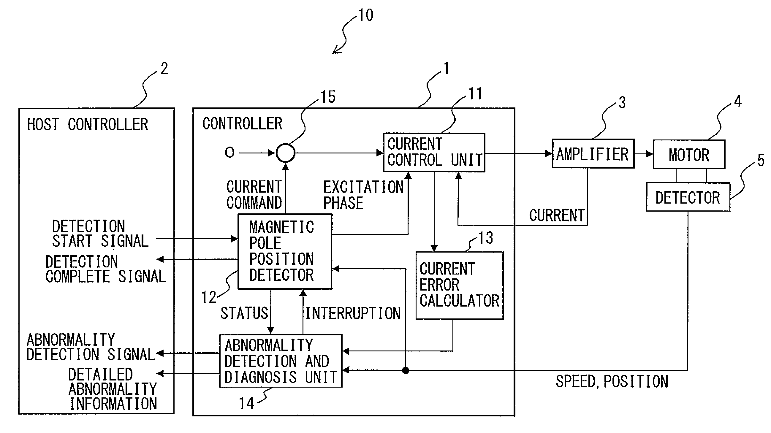
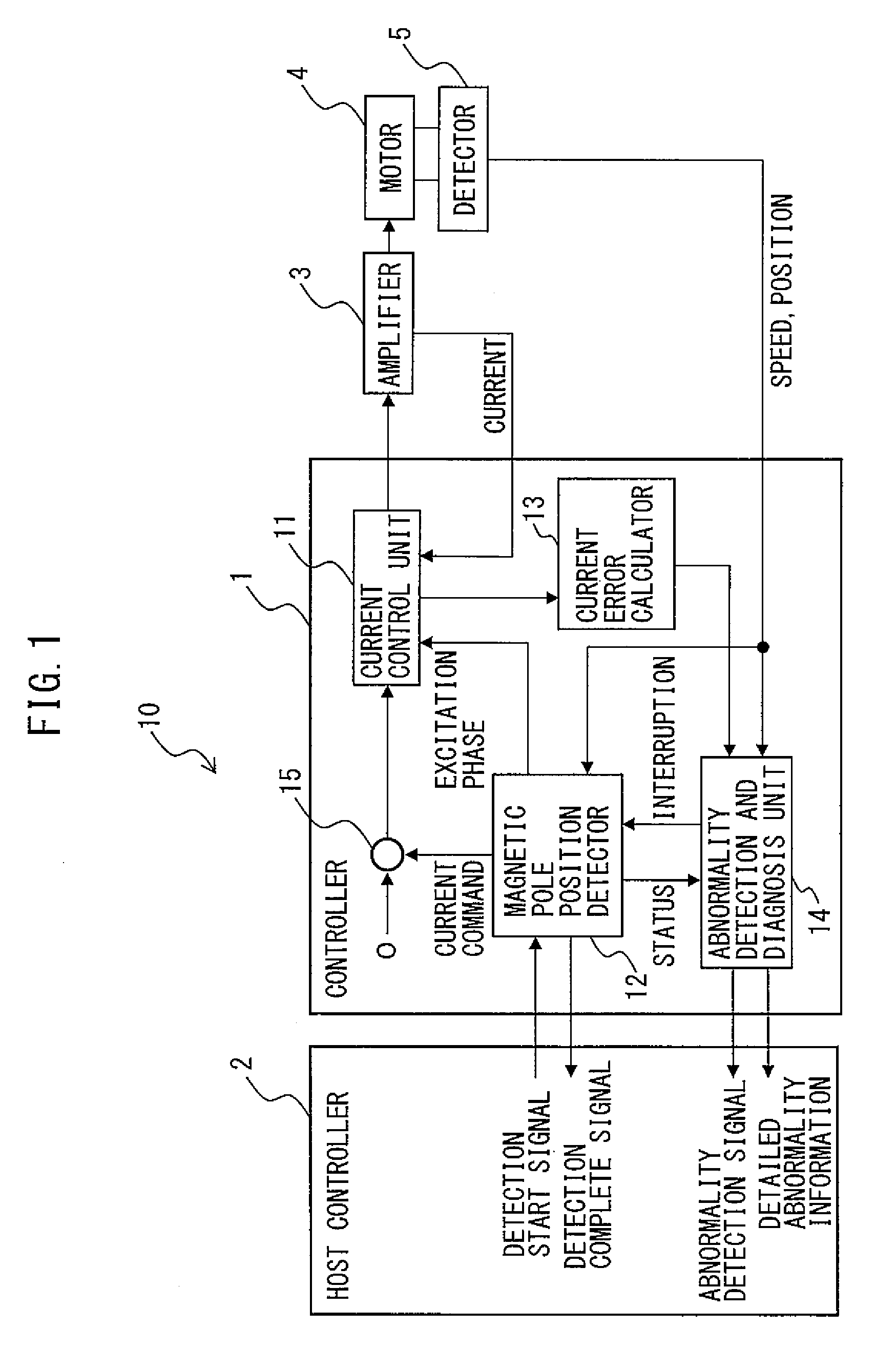
[0020]FIG. 1 is a configuration diagram of a control system for a motor according to an embodiment of the present invention. The control system 10 of an embodiment of the present invention includes a controller 1 for controlling operations of the motor 4 and a host controller 2 which provides an abnormality detection start command to the controller 1. The controller 1 includes a current control unit 11, a magnetic pole position detector 12, a current error calculator 13 and an abnormality detection and diagnosis unit 14.

[0021]In accordance with the magnetic pole position of a rotor of the motor 4 in which permanent magnets are disposed, the current control unit 11 p...


PUM


Abstract

A control system includes a current control unit providing, in accordance with the magnetic pole position of a rotor in which permanent magnets are disposed, a first current command to a first excitation phase of a stator winding and providing a second current command to a second excitation phase, a current error calculator calculating a current error which is a difference between a current flowing through the motor during the first period and the first current command or a difference between a current flowing through the motor during the second period and the second current command, and an abnormality detection and diagnosis unit detecting an abnormality based on the speed, the direction of movement and the amount of movement of the motor and the magnitude of the current error.

Description

CROSS-REFERENCE TO RELATED APPLICATIONS[0001]This application is a new U.S. patent application that claims benefit of JP 2013-052020, filed on Mar. 14, 2013, the content of JP 2013-052020 is incorporated herein by reference.FIELD OF THE INVENTION[0002]The present invention relates to a control system for a synchronous motor and, in particular, to a control system for a synchronous motor that includes an abnormality detection and diagnosis function.BACKGROUND OF THE INVENTION[0003]In the field of synchronous motors, a synchronous motor is controlled to pass a current in an appropriate excitation phase of a stator winding in accordance with a magnetic pole position of a rotor in which permanent magnets are disposed, thereby producing a desired torque. One known way to detect a magnetic pole position of the rotor is to use a magnetic pole sensor or the like designed for that purpose. Typically, an angle sensor for absolute angular measurement is used. To attach the angle sensor, a “mag...

Claims


Application Information

Patent Timeline
Patent Type & Authority Patents(United States)
IPC IPC(8): H02P1/46H02P6/16H02P29/02H02P6/12G01R31/34H02P21/22H02P25/022H02P27/06
CPCH02P6/12G01R31/343H02P6/165H02P29/021H02P6/17H02P29/0241
Inventor SONODA, NAOTO
Owner FANUC LTD
Why Eureka
Try Eureka