
Method and apparatus for performing super-resolution

a super-resolution and super-resolution technology, applied in the direction of instruments, video signal spatial resolution conversion, standards conversion, etc., can solve the problems of inability to use real-time applications, high cost, and inability to achieve proper working, so as to achieve effective frame-rate up-conversion and improve the spatial resolution of the input video sequence

Active Publication Date: 2016-02-09
INTERDIGITAL CE PATENT HLDG
View PDF1 Cites 6 Cited by
  • Summary
  • Abstract
  • Description
  • Claims
  • Application Information

AI Technical Summary

Benefits of technology

The proposed method in this patent text can correct motion-compensation in a wide range of movements, making it suitable for the parallel hardware in modern GPUs. It can even match the results of costly state-of-the-art methods for optical flow estimation. Additionally, the method improves the spatial resolution of the input video sequence by synthesizing high-frequency bands. This is done by considering a broader search range extended to the 3D domain.

Problems solved by technology

This operation is sped-up by means of a randomized-based search, which is highly costly.
Even though the method works impressively in the provided results, it is not clear that it would work properly in general sequences, with motions of different nature not recursively appearing at different spatial and temporal scales in the input video sequence.
Furthermore, the spatio-temporal search, even if not exhaustive, is a costly procedure which renders the approach unusable for real-time applications.
Two problems of this approach are that, first, the effect of the space-time steering filter is that of producing a non-linear over-smoothing of the region to be super-resolved, which requires a costly non-linear post-correction and loss of detail, and second that the approach is only capable of producing correctly interpolated frames under a limited subset of motion ranges, due to the mechanism for motion compensation (block matching).

Method used


Image

  • Method and apparatus for performing super-resolution
  • Method and apparatus for performing super-resolution
  • Method and apparatus for performing super-resolution

Examples


Embodiment Construction

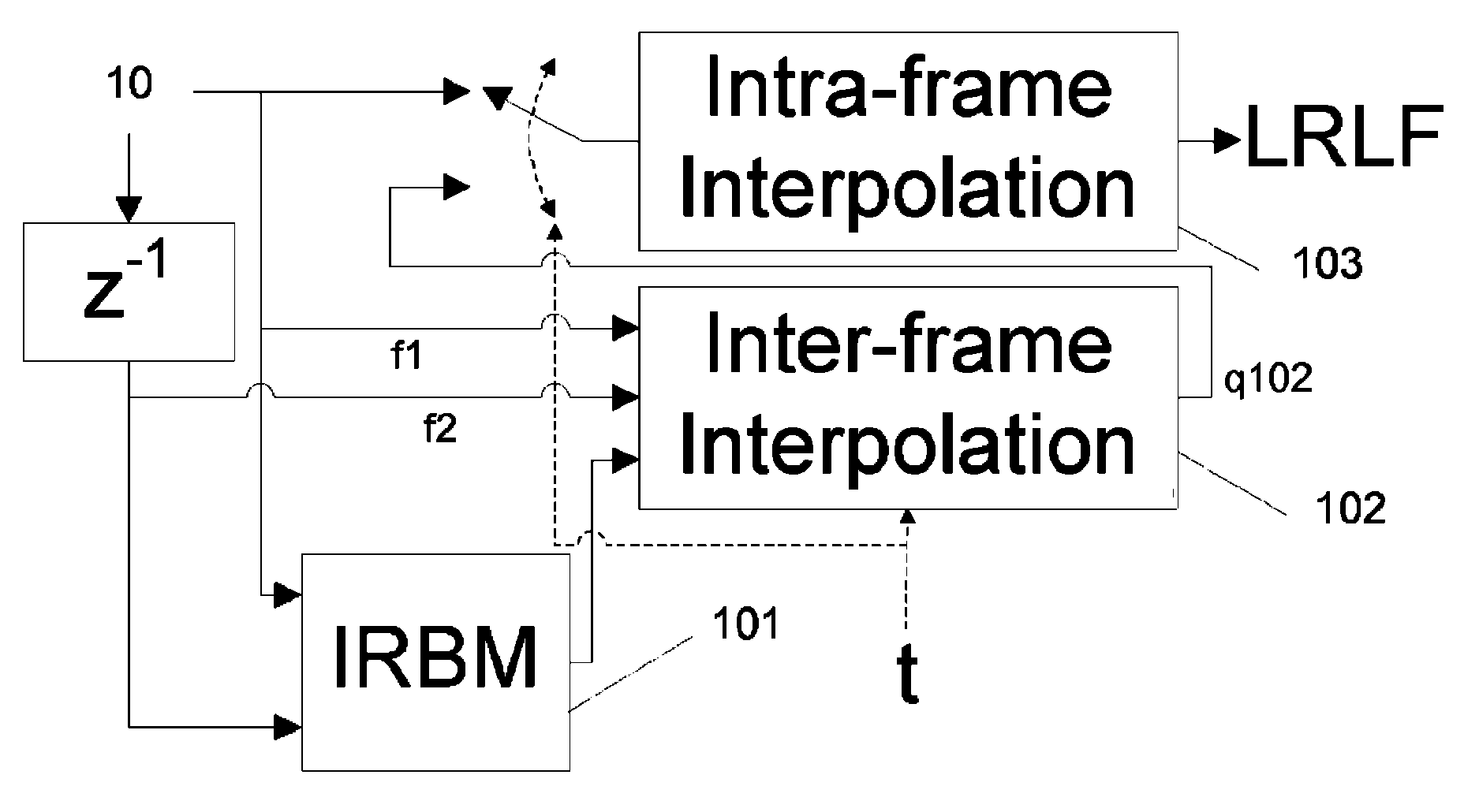
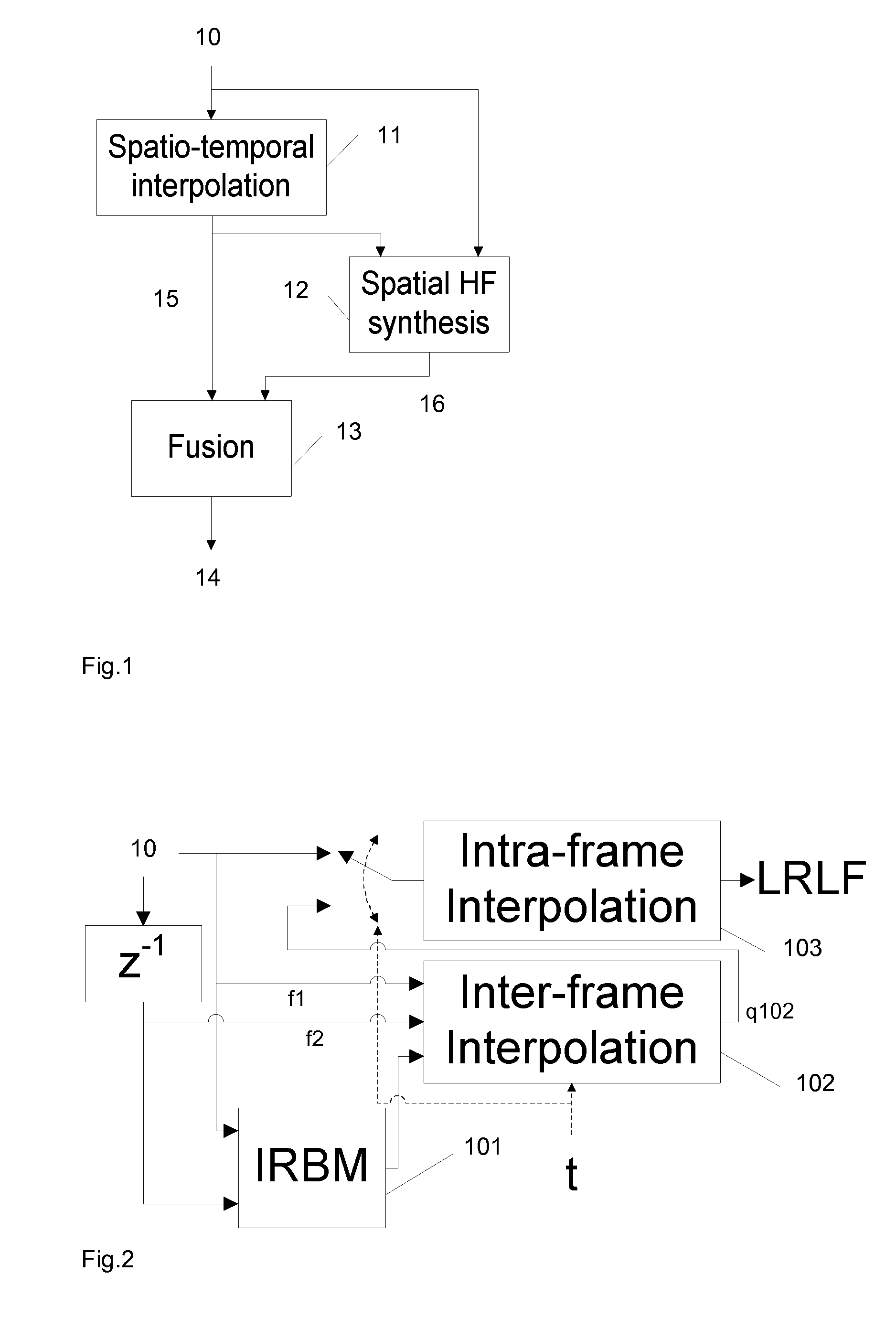
[0031]FIG. 1 shows the structure of the proposed system, in one embodiment. In FIG. 1, LR 10 is a low-resolution input video sequence, HRLF 15 is a high-resolution low-frequency interpolated band, HRHF 16 is a high-resolution high-spatial-frequency synthesized band and HR 17 is a resulting super-resolved video sequence, obtained after fusing the HRLF 15 and HRHF 16 bands. The high-resolution low-frequency HRLF interpolated band 15 is generated in spatio-temporal interpolation 11 that is applied to the low-resolution input video sequence 10. A spatial HF synthesis 12 is applied to the HRLF interpolated band 15, whereby also the original input sequence 10 is used. The spatial HF synthesis 12 produces a high-resolution high-spatial-frequency synthesized band 16. The HRLF interpolated band 15 and the HRHF synthesized band 16 are fused 13, which results in a super-resolved video sequence 14.

[0032]In the following, details of the Spatio-temporal interpolation 11 are described. The Spatio-...


PUM


Abstract

A method for performing super-resolution comprises steps of generating the high-resolution, low-frequency spatial and temporal bands of the input video sequence by interpolation, synthesizing the high-resolution, high-frequency spatial band by cross-frame spatial high-frequency extrapolation, and fusing these two bands to generate the spatio-temporally super-resolved video sequence. A corresponding system for performing super-resolution comprises a stage where the high-resolution, low-frequency spatial and temporal bands of the input video sequence is generated by interpolation, a stage where the high-resolution, high-frequency spatial band is synthesized by cross-frame spatial high-frequency extrapolation, and a stage where these two bands are fused to generate the spatio-temporally super-resolved video sequence.

Description

[0001]This application claims the benefit, under 35 U.S.C. §365 of International Application PCT / EP2013 / 054447, filed Mar. 5, 2013, which was published in accordance with PCT Article 21(2) on Sep. 12, 2013 in English and which claims the benefit of European patent application No. 12305265.6, filed Mar. 5, 2012.FIELD OF THE INVENTION[0002]This invention relates to a method and an apparatus for performing super-resolution (SR) in the temporal domain, or in the spatial and temporal domains.BACKGROUND OF THE INVENTION[0003]In “Space-Time Super-Resolution from a Single Video” by O. Shahar, A. Faktor and M. Irani (IEEE Conf. on Computer Vision and Pattern Recognition, 2011) [1], a space-time pyramid of the input video sequence is created containing several versions of the input video sequence at different spatial and temporal scales. Then, for each spatio-temporal video patch (with spatial dimensions of 5×5 pixels and temporal dimensions of 3 frames), a set of best matches is searched for...

Claims


Application Information

Patent Timeline
Patent Type & Authority Patents(United States)
IPC IPC(8): G06K9/32H04N7/01G06T3/40
CPCH04N7/0125G06T3/4053H04N7/0102H04N7/0117
Inventor SALVADOR, JORDIKOCHALE, AXELSCHWEIDLER, SIEGFRIED
Owner INTERDIGITAL CE PATENT HLDG
Learn More