
Radiographic system, drive control method for radiographic system, recording medium for drive control program and radiological image detection device

a drive control and radiographic system technology, applied in the direction of material analysis using wave/particle radiation, instruments, applications, etc., can solve the problems of difficult reception of the “irradiation stop signal” and the inability to stop x-ray irradiation irrespectively, and the inability to stop x-ray irradiation,

Active Publication Date: 2016-02-16
FUJIFILM CORP
View PDF16 Cites 14 Cited by
  • Summary
  • Abstract
  • Description
  • Claims
  • Application Information

AI Technical Summary

Benefits of technology

This solution effectively prevents unnecessary radiation exposure by ensuring radiation irradiation is stopped reliably, even in cases of communication failures, thereby ensuring patient safety and preventing radiation dose shortages.

Problems solved by technology

Accordingly, in a case where the reception of the “irradiation stop signal” is difficult due to communication failure, a problem that arises is that the X-ray irradiation is not stopped irrespective of reaching the target radiation dose.
Due to this, even when the radiation source control device does not receive the signal relating to the irradiation stop due to communication failure and the like and an accumulated radiation dose reaches the target radiation dose in both cases, a problem that the X-ray irradiation is not stopped may occur.
Since the signal is exchanged by wireless communication in which communication failure is easy to occur in JP2006-068507A, a possibility of a problem arising in that the X-ray irradiation is not stopped irrespective of reaching the target radiation dose is relatively high.

Method used


Image

  • Radiographic system, drive control method for radiographic system, recording medium for drive control program and radiological image detection device
  • Radiographic system, drive control method for radiographic system, recording medium for drive control program and radiological image detection device
  • Radiographic system, drive control method for radiographic system, recording medium for drive control program and radiological image detection device

Examples


Embodiment Construction

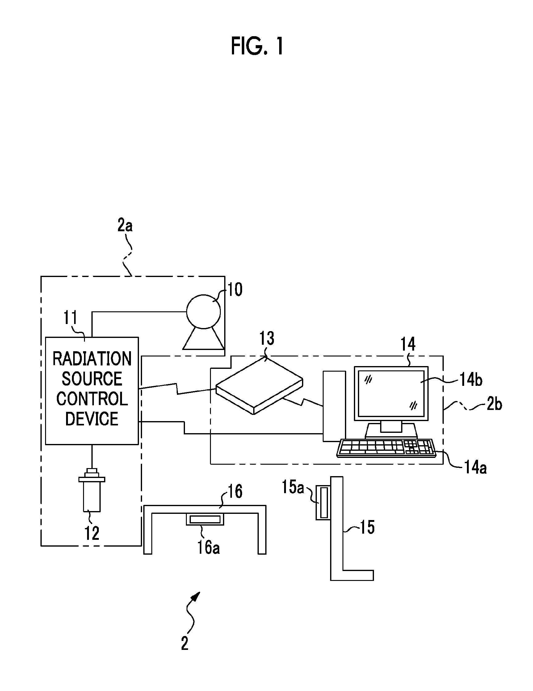
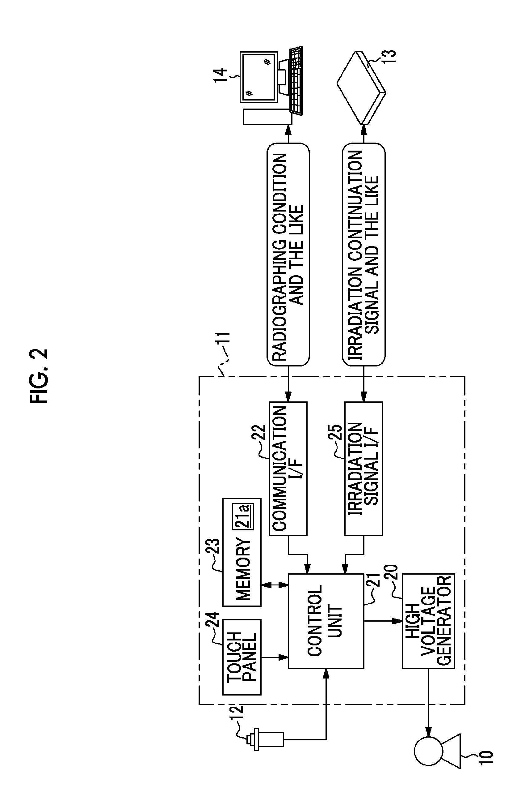
[0039]In FIG. 1, an X-ray radiographic system 2 has an X-ray source 10 in which an X-ray tube radiating X-rays is built, a radiation source control device 11 which controls the operations of the X-ray source 10, an irradiation switch 12 for instructing a start of the X-ray irradiation, an electronic cassette 13 which detects the X-ray passed through a subject and outputs an X-ray image, a console 14 (corresponding to a detection control device) which performs the operation control of the electronic cassette 13 and an image process of an X-ray image, an upright radiographic stand 15 for radiographing a subject in an upright posture, and a supine radiographic stand 16 for radiographing a subject in a supine posture. The X-ray source 10, the radiation source control device 11 and the irradiation switch 12 configure an X-ray generation device 2a, and the electronic cassette 13 and the console 14 configure an X-ray radiography device 2b, respectively. In addition, a radiation source movi...


PUM


Abstract

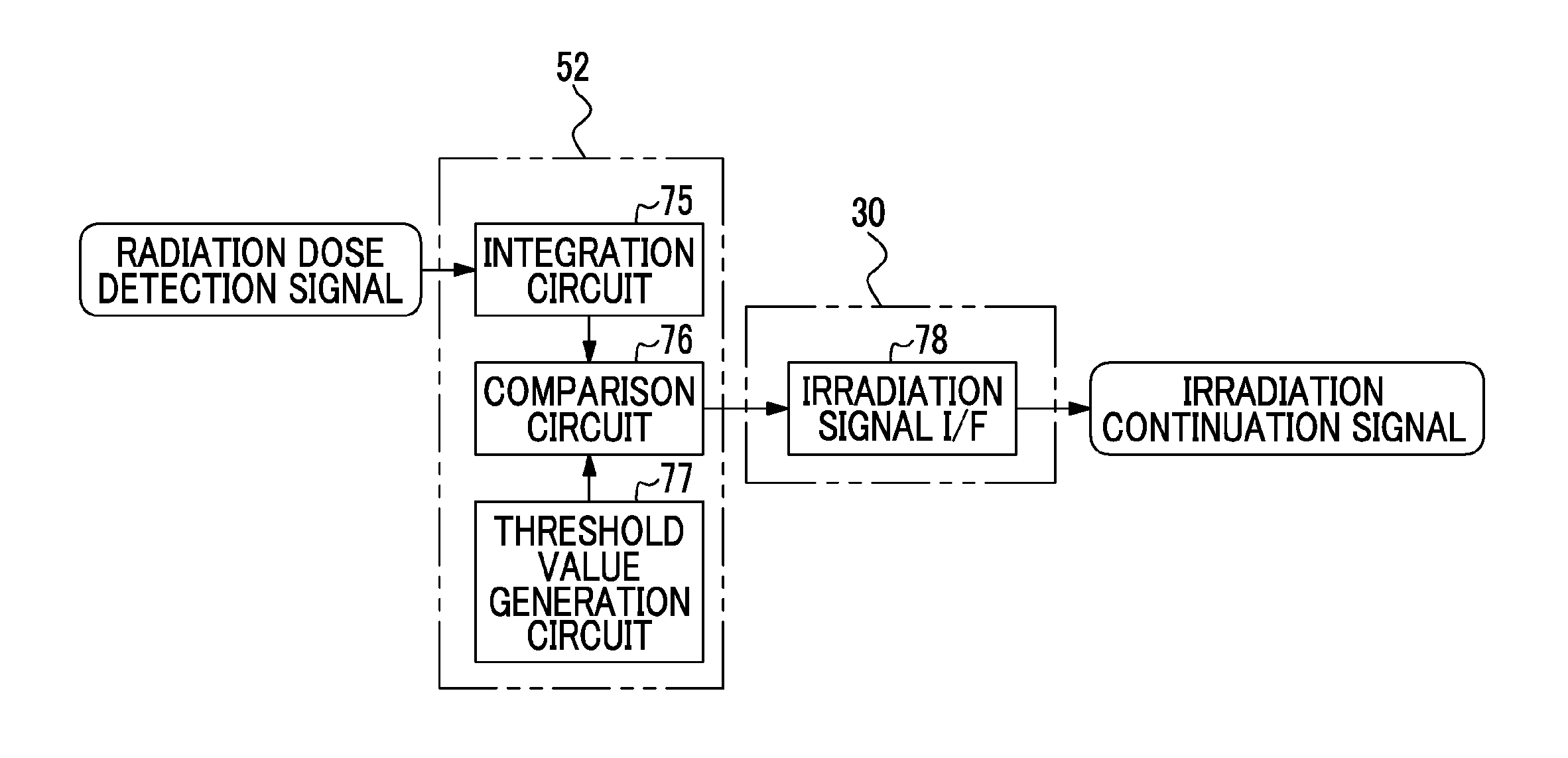
It is possible to reliably avoid a problem that radiation irradiation does not stop even when an accumulated radiation dose reaches a target radiation dose. An AEC unit starts monitoring an integrated value of a radiation dose detection signal from a detection pixel and an output of an irradiation continuation signal at the same time, and continuously transmits the irradiation continuation signal in a predetermined period while the integrated value does not reach a threshold value. When the integrated value reaches the threshold value, the output of the irradiation continuation signal is stopped. The irradiation continuation signal is transmitted to an irradiation signal I / F of a radiation source control device through an irradiation signal I / F by wireless. The radiation source control device stops X-ray irradiation by an X-ray source when the irradiation signal I / F does not receive the irradiation continuation signal.

Description

BACKGROUND OF THE INVENTION[0001]1. Field of the Invention[0002]The present invention relates to a radiographic system which performs automatic exposure control, a drive control method for a radiographic system, a drive control program and a radiological image detection device.[0003]2. Description of the Related Art[0004]In the medical field, an X-ray radiographic system that uses radiation such as X-rays is known. The X-ray radiographic system includes an X-ray generation device which generates X-rays and an X-ray radiographic device which receives X-rays and radiographs an X-ray image. The X-ray generation device has an X-ray source which irradiates a subject with X-rays, a radiation source control device which controls the driving of the X-ray source and an irradiation switch for inputting an X-ray irradiation start instruction. The X-ray radiographic device has an X-ray image detection device which receives X-rays that have passed through the subject and detects an X-ray image a...

Claims


Application Information

Patent Timeline
Patent Type & Authority Patents(United States)
IPC IPC(8): A61B6/00
CPCA61B6/542A61B6/4233
Inventor SATO, MASARU
Owner FUJIFILM CORP
Learn More