Turbine rotor

a turbine rotor and rotor body technology, applied in the field of turbine rotors, can solve the problems of increasing the stress concentration factor, affecting the strength or durability of the product, and the root part of the hub on the rear surface side, so as to reduce the rotational inertia increase the strength and durability of the turbine rotor, and reduce the stress concentration factor

Active Publication Date: 2016-02-16
MITSUBISHI HEAVY IND LTD
View PDF24 Cites 3 Cited by
  • Summary
  • Abstract
  • Description
  • Claims
  • Application Information

AI Technical Summary

Benefits of technology

[0044]The first aspect of the present invention can provide a turbine rotor in which the rotational inertia of the turbine rotor can be reduced without changing the geometry of the blade part, whereas the turbine rotor is provided with the rear side surface so that the stress concentration appearing at the root part regarding the hub part on the rear surface side is constrained. Thus, the strength and the durability of the turbine rotor can be enhanced.
[0045]Further, according to the second aspect of the present invention, as is the case with the first aspect of the present invention, the stress concentration factor can be reduced and the stress concentration can be constrained. Moreover, in the second aspect, the center of the arc of the circle is placed outside of the hub part as well as the rear side surface in a case where the cross-section of the annular recess includes the part as the arc of a circle; on the other hand, the major axis is placed outside of the hub part as well as the rear side surface in a case where the cross-section of the annular recess includes the part of the major arc of an oval shape or an egg shape.
[0046]In this way, the curvature radius along the cross-section of the second aspect can be made larger than the curvature radius along the cross-section of the first aspect, the cross-section of the first aspect being formed with a part of the major arc of an oval shape or an egg shape. Thus, the stress concentration appearing at the root part regarding the hub part on the rear surface side can be further constrained.

Problems solved by technology

In this way, in the conventional technologies as described above, there has been a difficulty that the stress concentration is inclined to be caused in the recess bottom area; in addition, there has been a difficulty that the stress concentration is also inclined to appear at the root part regarding the hub part on the rear surface side.
And, the difficulties accompany the problems regarding the strength or the durability of the product.

Method used


Image

  • Turbine rotor
  • Turbine rotor
  • Turbine rotor

Examples


Embodiment Construction

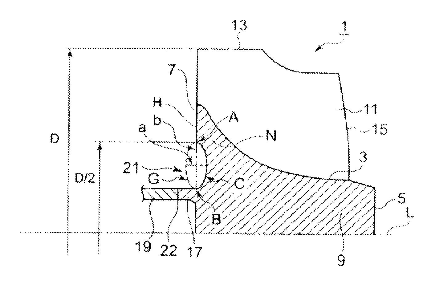
[0058]Hereafter, the present invention will be described in detail with reference to the modes or embodiments shown in the figures. However, the dimensions, materials, shape, the relative placement and so on of a component described in these modes or embodiments shall not be construed as limiting the scope of the invention thereto, unless especially specific mention is made.

(First Mode)

[0059]Based on the examples of the turbine rotors of the turbochargers for vehicle use, marine use and the like, the present invention is now explained. FIG. 1 shows a turbine rotor 1 according to a first mode of the present invention, in a cross section along the rotation axis direction; the turbine rotor 1 (hereafter also called simply as a rotor) forms a rotation body around the rotation axis in the axis direction; further, in the rotor, a hub part 9 including, but not limited to, a hub line surface (a hub surface) 3, a front side surface 5 and a rear side surface 7 is integrated with a plurality o...


PUM


Abstract

Providing a turbine rotor in which the rotational inertia of the turbine rotor can be reduced without changing the geometry of the blade part, whereas the turbine rotor is provided with the rear side surface so that the stress concentration appearing at the root part regarding the hub part on the rear surface side is constrained in order that the strength and the durability of the turbine rotor can be enhanced. A turbine rotor that comprises a hub part 9 connected to a rotor shaft 19 and a plurality of blade parts 11 formed around the outer periphery of the hub part 9, the hub part and the blade parts being integrated into one piece, wherein the diameter of the hub part 9 around the rotation axis L of the rotor shaft 19 gradually increases along the rotation axis direction toward a rear side surface 7 on an end side regarding the rotation axis direction; an annular recess 21 is formed annularly around the rotation axis as a rotation center line, on the side of the rear side surface 7 of the hub part 9; the cross-section of the annular recess whose plane includes the rotation axis is configured with a part of the major arc C of an oval shape or an egg shape, the major arc C being formed so that the oval shape or the egged shape is divided by the major axis b as a symmetrical axis of the oval shape or the egged shape; and, the major axis b is placed in the rear side surface 7.

Description

BACKGROUND OF THE INVENTION[0001]1. Field of the Invention[0002]The present invention relates to the turbine rotor of a radial or mixed flow type turbine that is used in turbochargers and the like; the present invention especially relates to the rear side surface geometry of the turbine rotor.[0003]2. Background of the Invention[0004]In the turbine rotors of the turbochargers used for vehicle engines, marine engines and the like, when turbine rotor has a great deal of rotational inertia (moment of inertia), the start-up characteristic regarding the engine speed as well as the charging air pressure is deteriorated, as shown in FIG. 7 that shows a response characteristic regarding the engine system in which the turbocharger is included; a result, a time lag regarding the response characteristic is generated between a time point when the inputted gas condition is changed and a time point when the engine speed as well as the charging air pressure is kept in a steady state.[0005]Accordin...

Claims


Application Information

Patent Timeline
Patent Type & Authority Patents(United States)
IPC IPC(8): F01D5/04F01D5/02F01D5/06
CPCF01D5/048F01D5/026F01D5/063F05D2230/232F05D2260/941F05D2250/14F05D2250/293F01D5/04F01D5/14
Inventor YOSHIDA, TOYOTAKAOSAKO, KATSUYUKIYOKOYAMA, TAKAOEBISU, MOTOKI
Owner MITSUBISHI HEAVY IND LTD
Why Eureka
Try Eureka