Torsional vibration damper

a torsional vibration and damper technology, which is applied in the direction of fluid gearings, belts/chains/gearings, mechanical instruments, etc., can solve the uneven angular velocity of the drivetrain, the centrifugal force acting on the centrifugal pendulum-type absorber, and the unevenness of the drivetrain. , to achieve the effect of improving the damping properties of the torsional vibration damper, low torsional vibration, and high speed

Active Publication Date: 2016-02-16
SCHAEFFLER TECH AG & CO KG
View PDF14 Cites 1 Cited by
  • Summary
  • Abstract
  • Description
  • Claims
  • Application Information

AI Technical Summary

Benefits of technology

[0006]The object of the present invention is therefore to provide an improved torsional vibration damper.
[0007]The present invention is a torsional vibration damper for a drivetrain of a motor vehicle, including a substantially discoidal centrifugal flange and a plurality of centrifugal pendulum-type absorbers. Each centrifugal pendulum-type absorber has a first pendulum mass and a second pendulum mass. The first pendulum mass is arranged above a first surface of the pendulum flange, and the second pendulum mass is arranged above a second surface of the pendulum flange. In addition, the first pendulum mass and the second pendulum mass of each centrifugal pendulum-type absorber are firmly connected to each other by means of at least two spacing bolts in each case. The pendulum flange has a plurality of cutouts in which the spacing bolts are guided, where a second spacing bolt of a first centrifugal pendulum-type absorber and a first spacing bolt of a second centrifugal pendulum-type absorber are guided in at least one first cutout. In addition, a spacing element is arranged in the first cutout that is dimensioned such that the first centrifugal pendulum-type absorber and second centrifugal pendulum-type absorber cannot contact each other. The spacing element then prevents the first centrifugal pendulum-type absorber and the second centrifugal pendulum-type absorber from impacting each other. This prevents the annoying development of noise even at low drivetrain speeds.
[0009]It is also preferable for the spacing element to be flat and have basically the same thickness as the pendulum flange. The spacing element can then be preferably arranged in the first cutout and does not cause any additional friction between the spacing element and the pendulum masses of the centrifugal pendulum-type absorber.
[0010]In one embodiment, the first cut out basically has the shape of an annular sector, and the spacing element also basically has the shape of an annular sector. This is a particularly simple design of the spacing element.
[0012]It is particularly preferable for the spacing element to have the shape of a bracket open toward the midpoint of the pendulum flange. The spacing element can then preferably easily slide off a radially outer boundary edge of the first cutout.

Problems solved by technology

Torsional vibration can arise in a drivetrain of a motor vehicle.
An uneven angular velocity of the drivetrain that, for example, is generated by the operating cycles of an internal combustion engine, causes deflections of the centrifugal pendulum-type absorbers in the circumferential direction of the pendulum flange, which attenuate the unevenness of the angular velocity of the drivetrain.
When the speed and angular velocity of the drivetrain are low, the centrifugal force acting on the centrifugal pendulum-type absorbers can, in certain circumstances, be insufficient to keep the centrifugal pendulum-type absorbers in their positions radially to the outside.
This generates noise that is perceived as annoying and problematic.

Method used


Image

  • Torsional vibration damper
  • Torsional vibration damper
  • Torsional vibration damper

Examples


Embodiment Construction

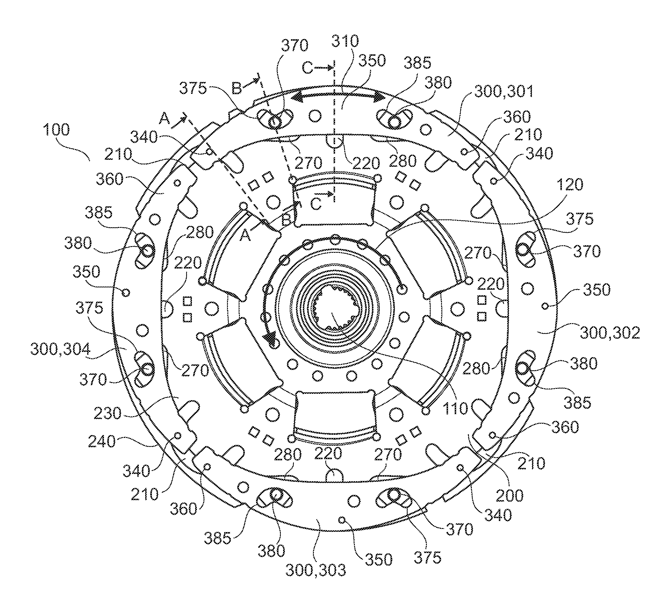
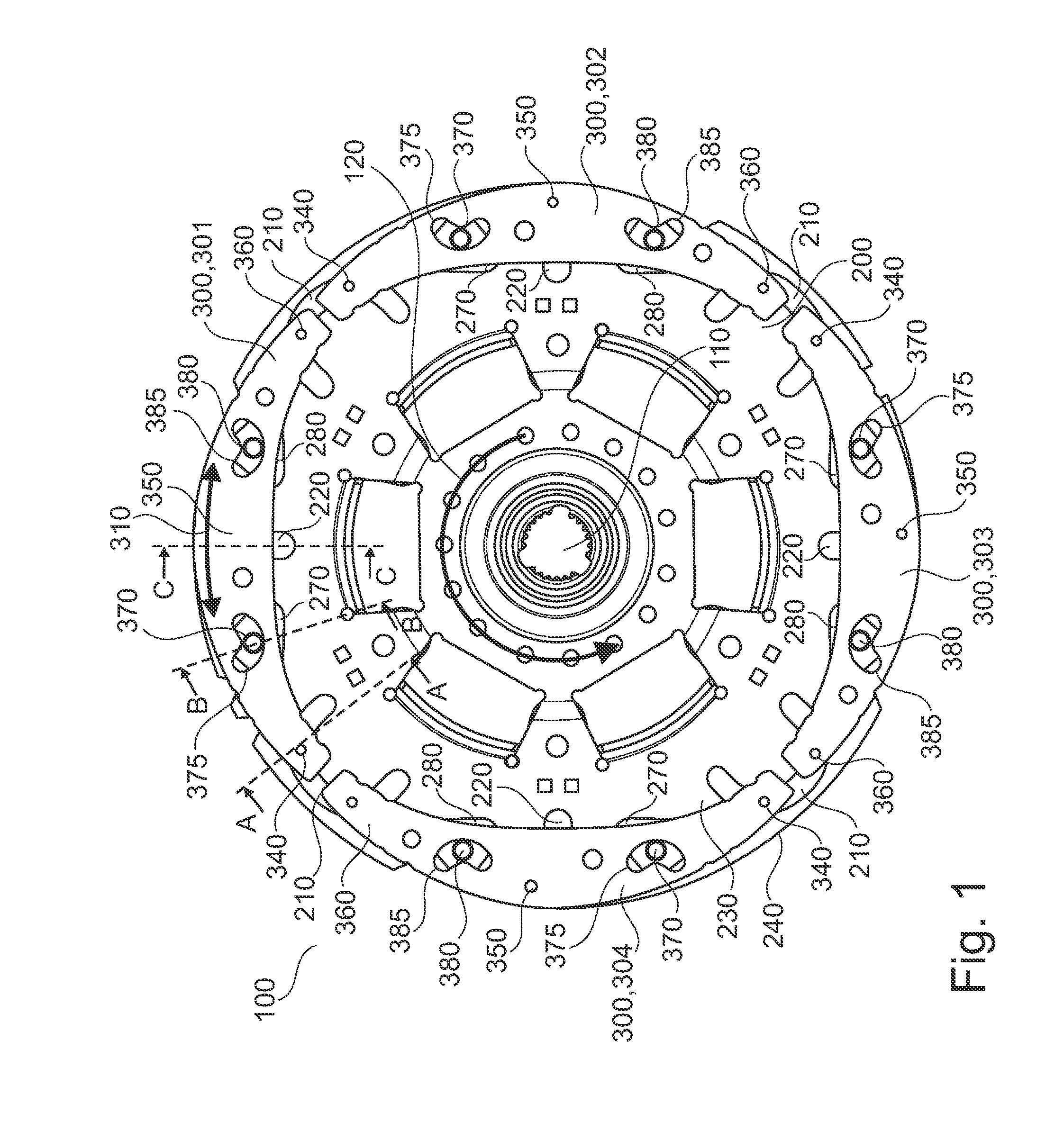
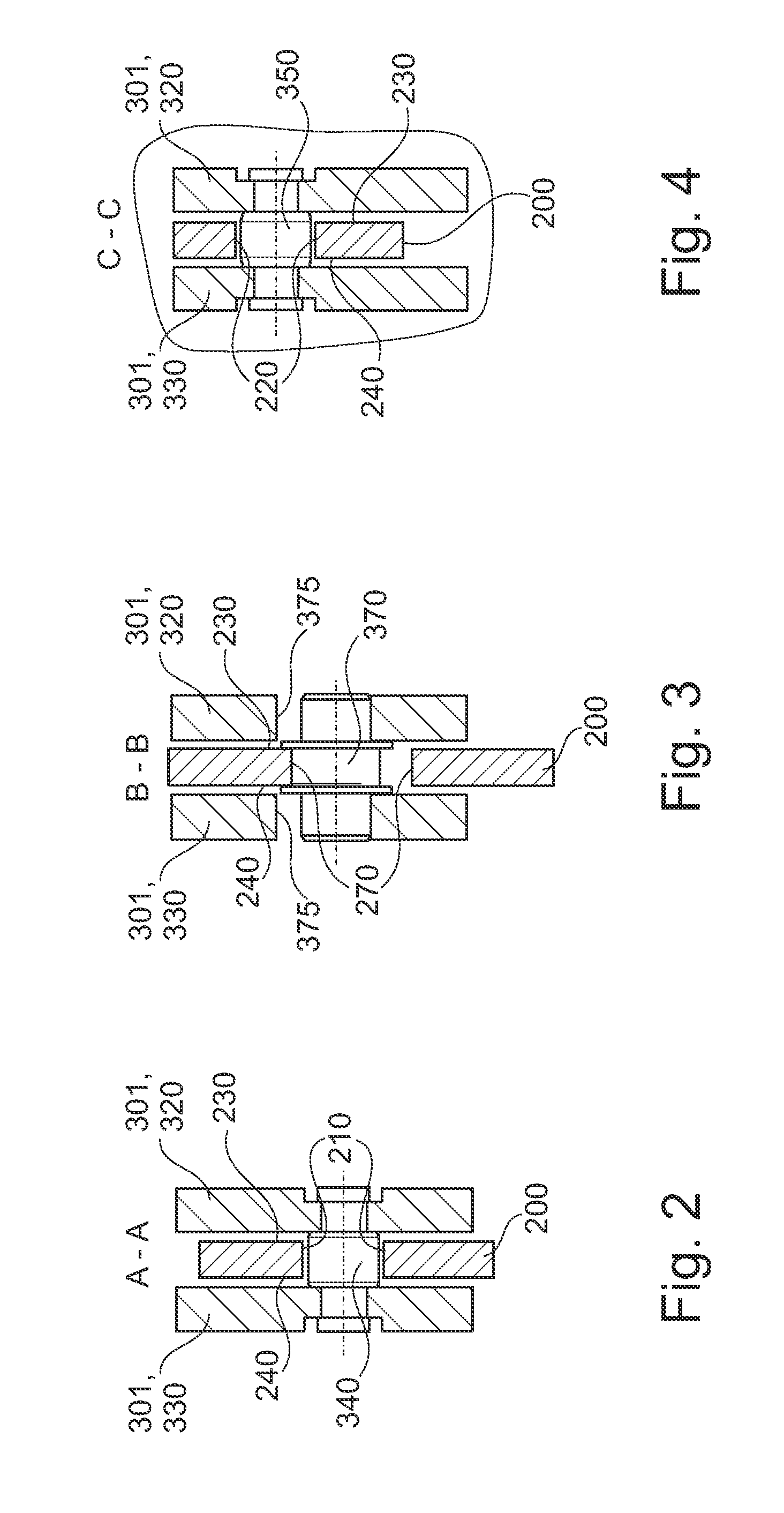
[0025]At the outset, it should be appreciated that like drawing numbers on different drawing views identify identical, or functionally similar, structural elements of the invention. While the present invention is described with respect to what is presently considered to be the preferred aspects, it is to be understood that the invention as claimed is not limited to the disclosed aspects.

[0026]Furthermore, it is understood that this invention is not limited to the particular methodology, materials and modifications described and, as such, may, of course, vary. It is also understood that the terminology used herein is for the purpose of describing particular aspects only, and is not intended to limit the scope of the present invention, which is limited only by the appended claims.

[0027]Unless defined otherwise, all technical and scientific terms used herein have the same meaning as commonly understood to one of ordinary skill in the art to which this invention belongs. Although any me...


PUM


Abstract

A torsional vibration damper for a drivetrain of a motor vehicle having a substantially discoidal centrifugal flange and a plurality of centrifugal pendulum-type absorbers. Each centrifugal pendulum-type absorber includes a first pendulum mass and a second pendulum mass. The first pendulum mass is arranged above a first surface of the pendulum flange, and the second pendulum mass is arranged above a second surface of the pendulum flange. The first pendulum mass and the second pendulum mass are firmly connected to each other by means of at least two spacing bolts in each case. The pendulum flange has a plurality of cutouts in which the spacing bolts are guided. A second spacing bolt of a first centrifugal pendulum-type absorber and a first spacing bolt of a second centrifugal pendulum-type absorber are guided in at least one first cutout.

Description

CROSS-REFERENCE TO RELATED APPLICATIONS[0001]This application is filed under 35 U.S.C. §120 and §365(c) as a continuation of International Patent Application PCT / DE2011 / 000197, filed Feb. 28, 2011, which application claims priority from German Patent Application No. 10 2010 011 142.2, filed Mar. 11, 2010, German Patent Application No. 10 2010 027 404.6, filed Jul. 15, 2010, German Patent Application No. 10 2010 031 989.9, filed Jul. 22, 2010, and German Patent Application No. 10 2010 051 860.3, filed Nov. 18, 2010, which applications are incorporated herein by reference in their entireties.FIELD OF THE INVENTION[0002]The present invention relates to a torsional vibration damper.BACKGROUND OF THE INVENTION[0003]Torsional vibration can arise in a drivetrain of a motor vehicle. To suppress this torsional vibration, it is known to use torsional vibration dampers arranged in the drivetrain. Such torsional vibration dampers or rotational vibration dampers consist of a substantially discoi...

Claims


Application Information

Patent Timeline
Patent Type & Authority Patents(United States)
IPC IPC(8): F16F15/30F16F15/123F16F15/14F16H45/02
CPCF16F15/30F16F15/123F16F15/145F16H2045/0263Y10T74/2128
Inventor JUNG, STEFANSCHNAEDELBACH, DAVIDWERNER, MARKUSHUEGEL, CHRISTIANMAIENSCHEIN, STEPHANKRAUSE, THORSTEN
Owner SCHAEFFLER TECH AG & CO KG
Why Eureka
Try Eureka