
Crankshaft structure of in-line three-cylinder engine

An engine and crankshaft technology, applied in the directions of engine components, crankshafts, shafts, etc., can solve the problems of poor strength performance and large torsional vibration amplitude, and achieve the effect of improving strength, reducing torsional vibration amplitude, and facilitating processing

Inactive Publication Date: 2016-10-12
GUANGXI YUCHAI MASCH CO LTD
View PDF6 Cites 1 Cited by
  • Summary
  • Abstract
  • Description
  • Claims
  • Application Information

AI Technical Summary

Problems solved by technology

[0004] The purpose of the present invention is to provide a crankshaft structure of an in-line three-cylinder engine, thereby overcoming the shortcomings of the existing crankshaft with large torsional vibration amplitude and poor strength performance

Method used


Image

  • Crankshaft structure of in-line three-cylinder engine
  • Crankshaft structure of in-line three-cylinder engine
  • Crankshaft structure of in-line three-cylinder engine

Examples


Embodiment Construction

[0025] The specific embodiments of the present invention will be described in detail below in conjunction with the accompanying drawings, but it should be understood that the protection scope of the present invention is not limited by the specific embodiments.

[0026] Unless expressly stated otherwise, throughout the specification and claims, the term "comprise" or variations thereof such as "includes" or "includes" and the like will be understood to include the stated elements or constituents, and not Other elements or other components are not excluded.

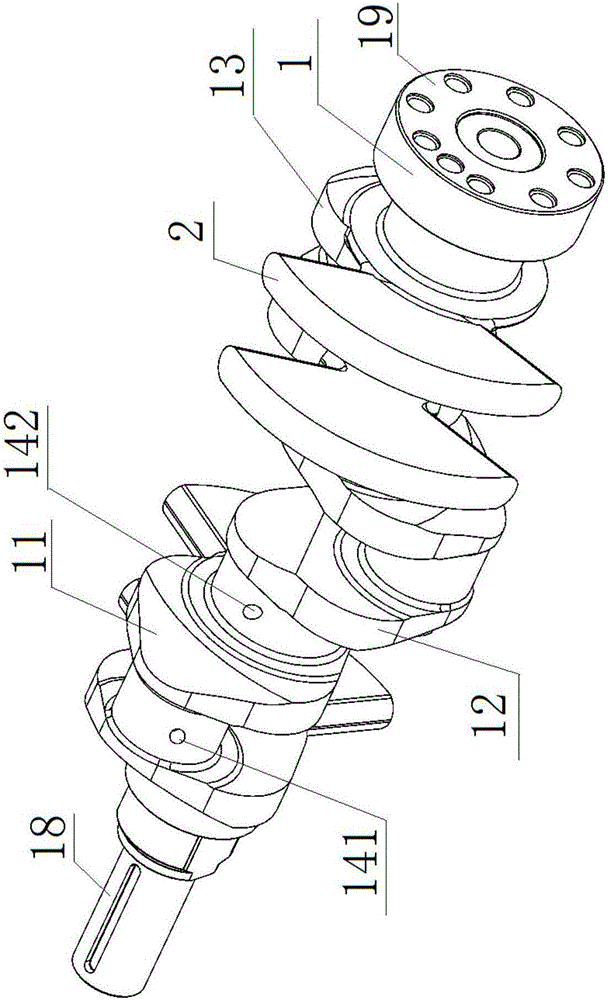
[0027] Such as figure 1 As shown, the crankshaft structure of the inline three-cylinder engine according to the specific embodiment of the present invention includes a crankshaft 1 and four counterweights 2 .

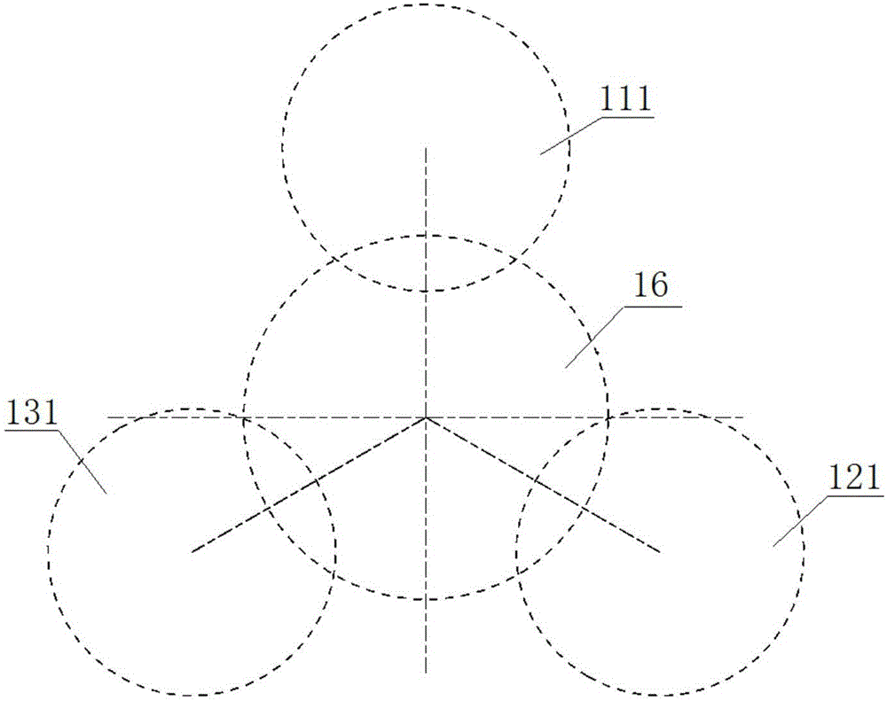
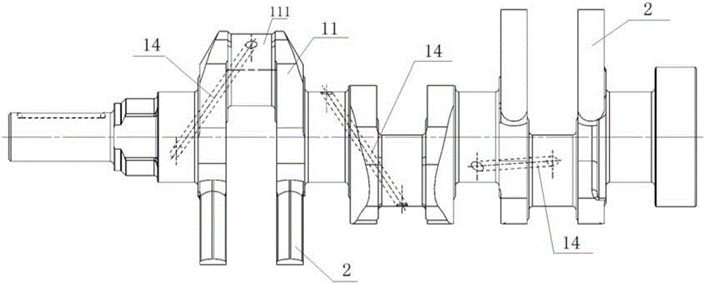
[0028] Such as Figure 1-4 As shown, the two ends of the crankshaft 1 are respectively the free end 18 and the power output end 19, projected along the direction from the free end 18 to the power output end 19, the...


PUM


Abstract

The invention discloses a crankshaft structure of an in-line three-cylinder engine. Two ends of the crankshaft are a free end and a power output end, projection is carried out along a direction from the free end to the power output end, a first toggle, a second toggle and a third toggle are sequentially arranged along the clockwise direction, an included angle between the first toggle and the second toggle and between the second toggle and the third toggle is 120DEG, and the firing order of the crankshaft is 1-2-3. The firing order is in favor of reducing the torsional vibration amplitude of a crankshaft system and improving the strength, the torsional oscillation and the strength of the crankshaft.

Description

technical field [0001] The invention relates to the field of engines, in particular to a crankshaft structure of an in-line three-cylinder engine. Background technique [0002] The torsional vibration amplitude of the crankshaft of the existing in-line three-cylinder engine is large, and the strength performance of the crankshaft is poor, and the oil supply capacity of the three-cylinder crankshaft is poor, and the oil passage arrangement is difficult and difficult to process. [0003] The information disclosed in this Background section is only for enhancing the understanding of the general background of the present invention and should not be taken as an acknowledgment or any form of suggestion that the information constitutes the prior art that is already known to those skilled in the art. Contents of the invention [0004] The object of the present invention is to provide a crankshaft structure of an in-line three-cylinder engine, so as to overcome the existing shortco...

Claims


Application Information

Patent Timeline
IPC IPC(8): F16C3/06F16F15/26
CPCF16C3/06F16C2360/00F16F15/26
Inventor 黄第云
Owner GUANGXI YUCHAI MASCH CO LTD
Learn More