
Torsional Vibration Damper And Start-Up Element

a technology of torsional vibration and start-up element, which is applied in the direction of fluid gearings, couplings, gearings, etc., can solve the problems of torsional vibration, perceived as annoying, and torsional vibration caused

Inactive Publication Date: 2017-10-05
ZF FRIEDRICHSHAFEN AG
View PDF2 Cites 0 Cited by
  • Summary
  • Abstract
  • Description
  • Claims
  • Application Information

AI Technical Summary

Benefits of technology

The patent text describes an improved design for damping torsional vibrations that involves a combination of two stages of a torsional vibration damper with a tuned mass vibration damper that has progressive characteristics. This design allows for better damping of torsional vibrations without negatively impacting the production, installation, and reliability of the damper. The distance between the transition points of the damper's progressive characteristics also helps to prevent abrupt changes in the damping behavior and prevents sudden back-coupling with other components. The use of this design can improve installation space efficiency and facilitate production and assembly of individual components.

Problems solved by technology

Torsional vibrations can be caused through the engine that is used to generate the rotational movement, but they can also be caused by discontinuous loads or abrupt withdrawals of power.
They may also be perceived as annoying when they produce noise or vibrations, for example.
By reason of its construction and design, the latter often produces an abrupt development of force and torque that can lead to the above-described torsional vibrations even as the rotational movement is generated.
However, this concept, also known as downsizing and downspeeding, can result in a further exacerbation of the problem brought about by rotational irregularities and torsional vibrations.
Thus the torsional vibrations are not only perceived as unpleasant and accordingly contribute to loss of comfort but, beyond this, they can also result in a shortening of service life, for example, because of occurring vibrations.
Although the example above is taken from vehicle engineering, more precisely automotive engineering, similar examples and sets of problems also occur in other areas of mechanical engineering, plant engineering and vehicle engineering.

Method used


Image

  • Torsional Vibration Damper And Start-Up Element
  • Torsional Vibration Damper And Start-Up Element
  • Torsional Vibration Damper And Start-Up Element

Examples


Embodiment Construction

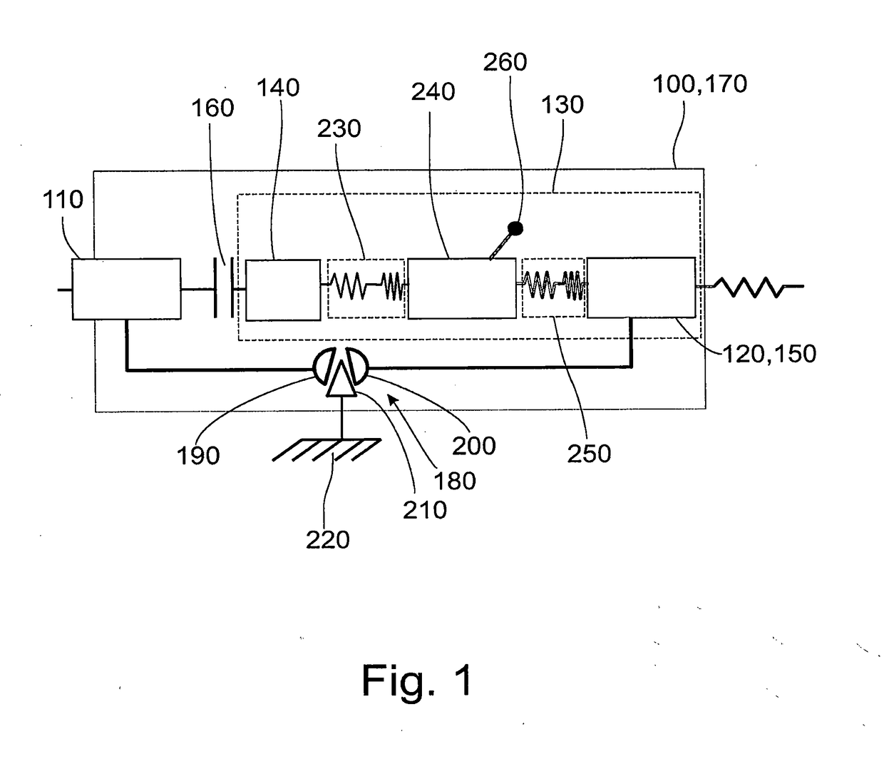
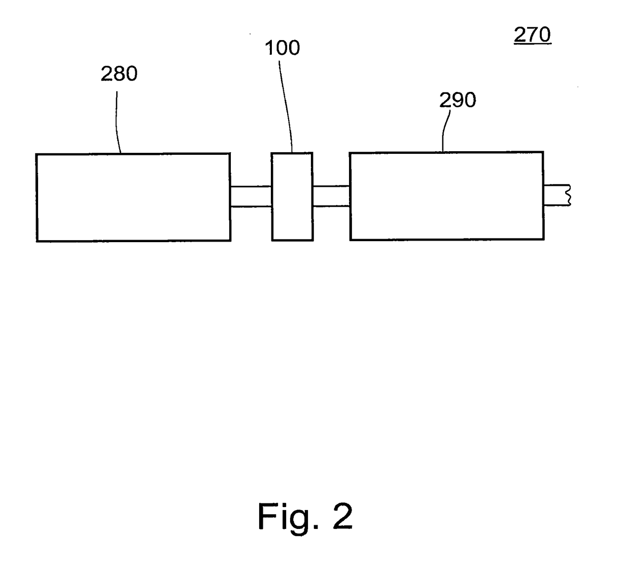
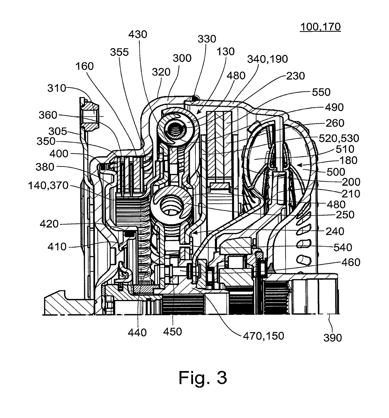
[0059]Identical or comparable components are denoted by identical reference numerals in the following description of the accompanying drawings. Further, collective reference numerals are used for components and objects which occur more than once in an embodiment example or diagram but which are described collectively with respect to one or more features. Components or objects which are denoted by identical reference numerals or collective reference numerals may be constructed identically or possibly also differently with respect to one or more or all features, for example, their dimensions, unless otherwise explicit or implicit from the description.

[0060]In many areas of plant engineering, mechanical engineering and vehicle engineering, a challenge consists in removing, or at least damping, one or more torsional vibration components from a rotational movement. Corresponding torsional vibration components of a rotational movement can occur in prime movers operating on the principle o...


PUM


Abstract

A torsional vibration damper has an input, an output and an intermediate mass arranged therebetween, a first plurality of spring elements coupled between the input and the intermediate mass that form a first stage, a second plurality of spring elements coupled between the intermediate mass and the output that form a second stage of the torsional vibration damper, at least one damper mass to damp the vibration component of the rotational movement. The first stage of the torsional vibration damper has a progressive first characteristic with at least one transition point. The second stage of the torsional vibration damper has a progressive, second characteristic with at least one transition point. All of the transition points of the first characteristic and the second characteristic are spaced apart from one another with respect to torque.

Description

CROSS REFERENCE TO RELATED APPLICATIONS[0001]This is a U.S. national stage of application No. PCT / EP2015 / 068614, filed on Aug. 13, 2015. Priority is claimed on German Application No. DE102014218926.8, filed Sep. 19, 2014, the content of which is incorporated here by reference.BACKGROUND OF THE INVENTION1. Field of the Invention[0002]Embodiment examples are directed to a torsional vibration damper and a start-up element such as can be used within the framework of a powertrain of a motor vehicle and to a corresponding powertrain for a motor vehicle.2. Description of the Prior Art[0003]In many areas of mechanical engineering, plant engineering and vehicle engineering, rotational movements are used to transmit mechanical energy. In this regard, it can happen for various reasons that one or more torsional vibrations are superimposed on a rotational movement of this kind. Torsional vibrations can be caused through the engine that is used to generate the rotational movement, but they can a...

Claims


Application Information

Patent Timeline
IPC IPC(8): F16D3/12F16F15/123
CPCF16D3/12F16F15/1234F16F15/12366F16H2045/0226F16F2232/02F16H45/02F16F2222/08F16F15/13484
Inventor HERTEL, MARTINWINTERSTEIN, MICHAELSUDAU, JOERGSTURMER, ARMINWEBER, CHRISTIANSASSE, CHRISTOPHKRUGER, THOMASWACK, ERWIN
Owner ZF FRIEDRICHSHAFEN AG
Learn More