
Lithographic apparatus and device manufacturing method

a technology of lithographic apparatus and manufacturing method, which is applied in the direction of microlithography exposure apparatus, printers, instruments, etc., can solve the problems of affecting reducing the accuracy of positioning, so as to achieve accurate vertical positioning of the target portion and the accurate positioning of the substra

Active Publication Date: 2016-02-16
ASML NETHERLANDS BV
View PDF14 Cites 0 Cited by
  • Summary
  • Abstract
  • Description
  • Claims
  • Application Information

AI Technical Summary

Benefits of technology

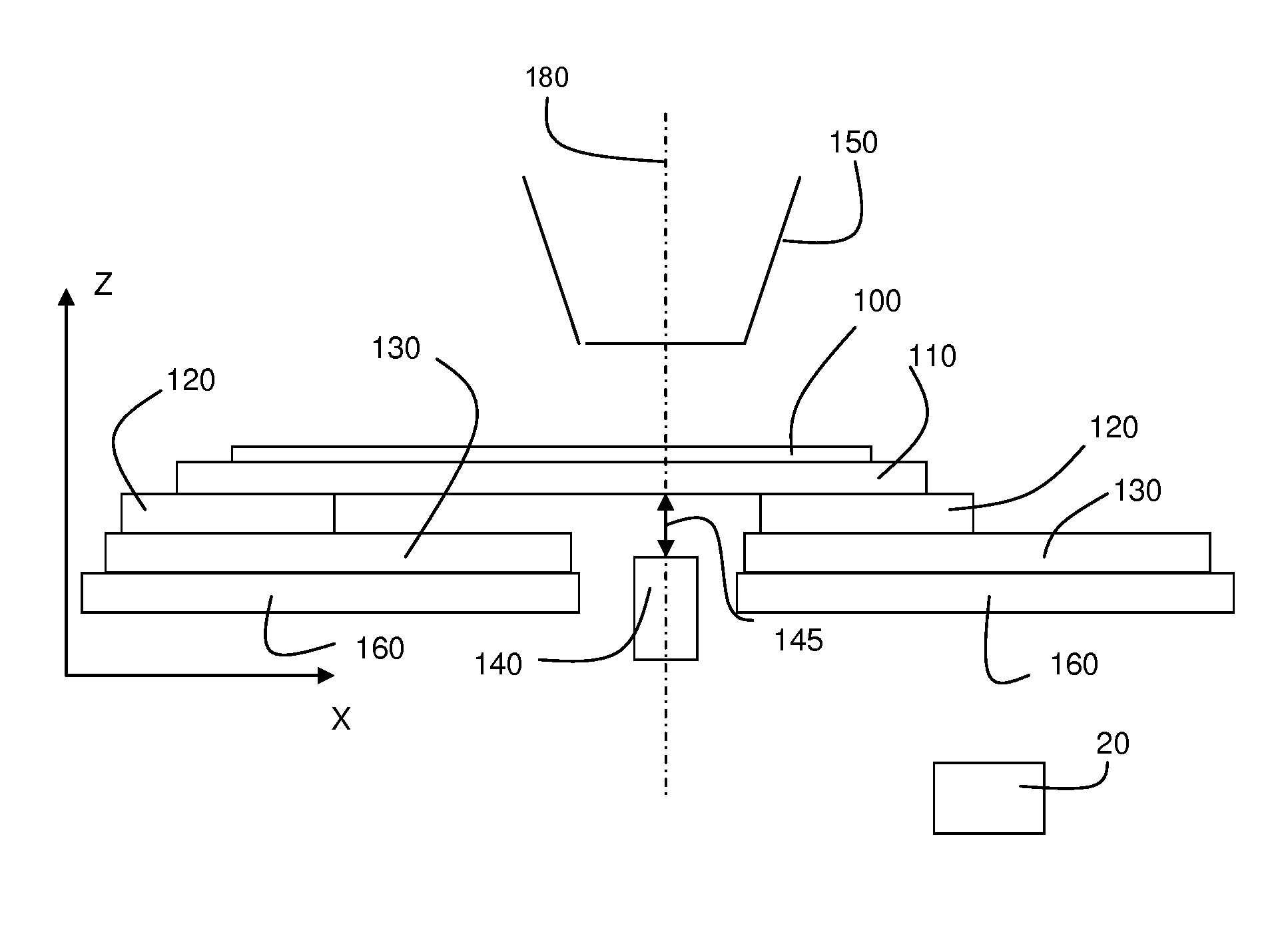
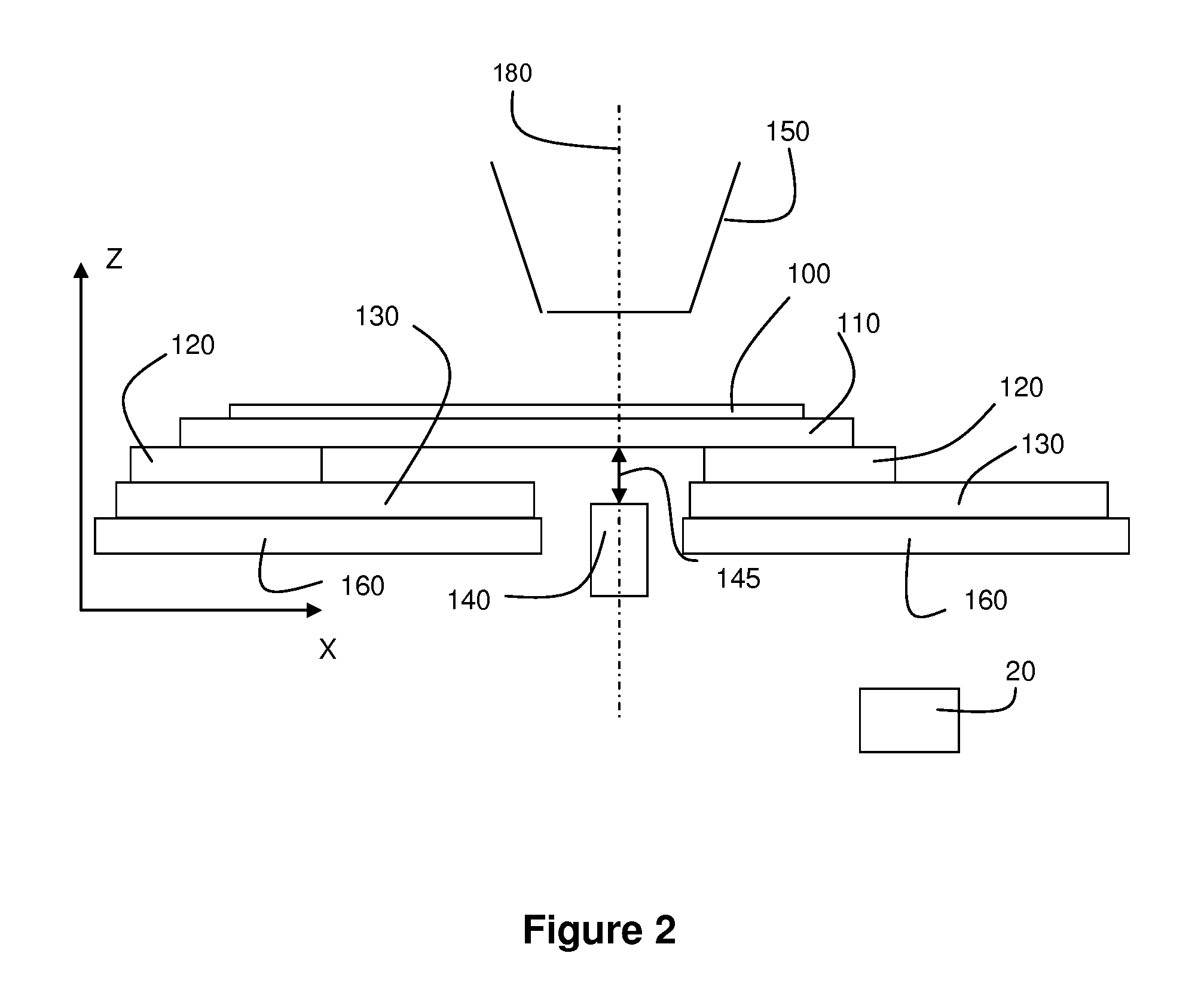
[0006]It is desirable to provide a substrate stage or lithographical apparatus that enables a more accurate positioning of a substrate, in particular a more accurate vertical positioning of a target portion relative to a projection system.

Problems solved by technology

In view of an increase in the accuracy requirements for the positioning of the substrate relative to the patterned radiation beam, more complex positioning devices have been designed.
It is expected that meeting the overlay and focus requirements will become more and more difficult, in particular when a transition is made towards larger wafers or substrates, such as 450 mm wafers.
Further, external disturbances as e.g., caused by liquid containing devices that are used in immersion lithographical apparatuses may further hinder an accurate positioning, in particular with respect to focusing of a substrate.

Method used


Image

  • Lithographic apparatus and device manufacturing method
  • Lithographic apparatus and device manufacturing method
  • Lithographic apparatus and device manufacturing method

Examples


Embodiment Construction

[0022]This specification discloses one or more embodiments that incorporate the features of this invention. The disclosed embodiment(s) merely exemplify the invention. The scope of the invention is not limited to the disclosed embodiment(s). The invention is defined by the claims appended hereto.

[0023]The embodiment(s) described, and references in the specification to “one embodiment”, “an embodiment”, “an example embodiment”, etc., indicate that the embodiment(s) described may include a particular feature, structure, or characteristic, but every embodiment may not necessarily include the particular feature, structure, or characteristic. Moreover, such phrases are not necessarily referring to the same embodiment. Further, when a particular feature, structure, or characteristic is described in connection with an embodiment, it is understood that it is within the knowledge of one skilled in the art to effect such feature, structure, or characteristic in connection with other embodimen...


PUM

PropertyMeasurementUnit
incident angleaaaaaaaaaa
wavelengthaaaaaaaaaa

Abstract

A substrate stage is used in a lithographic apparatus. The substrate stage includes a substrate table constructed to hold a substrate and a positioning device for in use positioning the substrate table relative to a projection system of the lithographic apparatus. The positioning device includes a first positioning member mounted to the substrate table and a second positioning member co-operating with the first positioning member to position the substrate table. The second positioning member is mounted to a support structure. The substrate stage further comprises an actuator that is arranged to exert a vertical force on a bottom surface of the substrate table at a substantially fixed horizontal position relative to the support structure.

Description

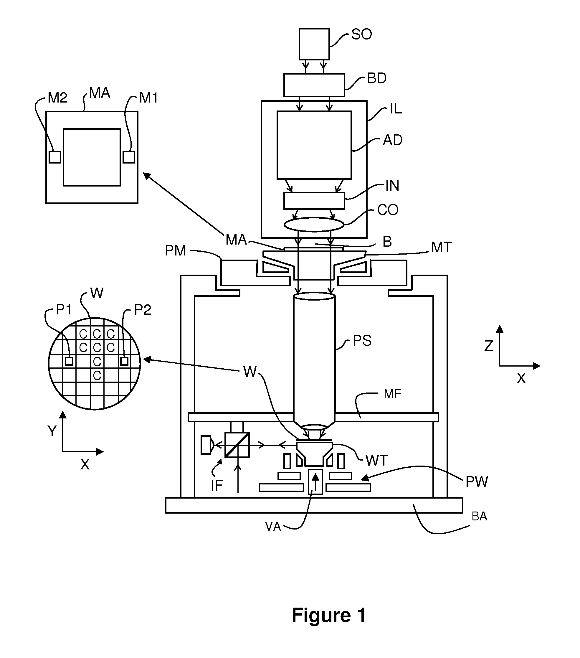
CROSS REFERENCE TO RELATED APPLICATIONS[0001]This application is related to and incorporates by reference herein in its entirety U.S. Provisional Application No. 61 / 650,708.BACKGROUND[0002]1. Field of the Present Invention[0003]The present invention relates to a substrate stage, a lithographic apparatus and a method for manufacturing a device.[0004]2. Description of the Related Art[0005]A lithographic apparatus is a machine that applies a desired pattern onto a substrate, usually onto a target portion of the substrate. A lithographic apparatus can be used, for example, in the manufacture of integrated circuits (ICs). In such a case, a patterning device, which is alternatively referred to as a mask or a reticle, may be used to generate a circuit pattern to be formed on an individual layer of the IC. This pattern can be transferred onto a target portion (e.g., including part of, one, or several dies) on a substrate (e.g., a silicon wafer). Transfer of the pattern is typically via imag...

Claims


Application Information

Patent Timeline
Patent Type & Authority Patents(United States)
IPC IPC(8): G03F7/20
CPCG03F7/70725G03F7/70758G03F7/70775
Inventor HUANG, YANG-SHANCADEE, THEODORUS PETRUS MARIA
Owner ASML NETHERLANDS BV
Learn More