Method of 3D model morphing driven by facial tracking and electronic device using the method the same

a 3d model and facial tracking technology, applied in the field of 3d model morphing, can solve the problems of high inconvenience and non-intuitiveness of putting such large number of color-dot tags on the fa

Active Publication Date: 2016-02-16
ULSEE
View PDF22 Cites 8 Cited by
  • Summary
  • Abstract
  • Description
  • Claims
  • Application Information

AI Technical Summary

Benefits of technology

[0006]It is one of the objectives of the present invention to provide a method of 3D morphing driven by facial tracking that does not require pasting of large number of color-dot tags on the subject.
[0015]According to an embodiment of the present invention, a method for achieving morphing effects on specified individual region of a real-time facial image of a person to obtain more exaggerated bigger movements is provided.

Problems solved by technology

However, it's highly inconvenient and non-intuitive to paste such large number of color-dot tags on the face.

Method used


Image

  • Method of 3D model morphing driven by facial tracking and electronic device using the method the same
  • Method of 3D model morphing driven by facial tracking and electronic device using the method the same
  • Method of 3D model morphing driven by facial tracking and electronic device using the method the same

Examples


first embodiment

[0052]FIG. 5 (including FIG. 5A and FIG. 5B) are diagrams illustrating a facial feature control point pickup method according to the present invention. In FIG. 5, the facial feature control points are picked up by user. In other words, there is a reference picture or image showing the operating rules for users that the numbers and the order of picked up facial feature control points of the 3D model should match those of the tracking points of the real-time facial image of the person. In addition, the position or location of the picked up facial feature control points can be revised by dragging the cursor using a mouse or a touch screen.

second embodiment

[0053]FIG. 6 is a diagram illustrating a control point reassignment and reconfiguration method according to the present invention. Upon using the A.config by the facial tracking algorithm (see Steps S305 and S306) as described in FIG. 3, the tracking points of the real-time facial image are picked up by the facial tracking algorithm. For example, as shown superimposed on the corresponding 3D model, the bigger red facial feature control points are showing that the respective corresponding matching tracking points located at the same location on the facial image captured in real-time are not accurate enough, therefore, the user can manually adjust some of the facial feature control points to compensate or overcome the inaccuracies of the tracking points' locations (located at the bigger red control points). In other words, after the tracking points are obtained by facial tracking, the user can correct the assigned locations for some of the inaccurate facial feature control points to o...

fourth embodiment

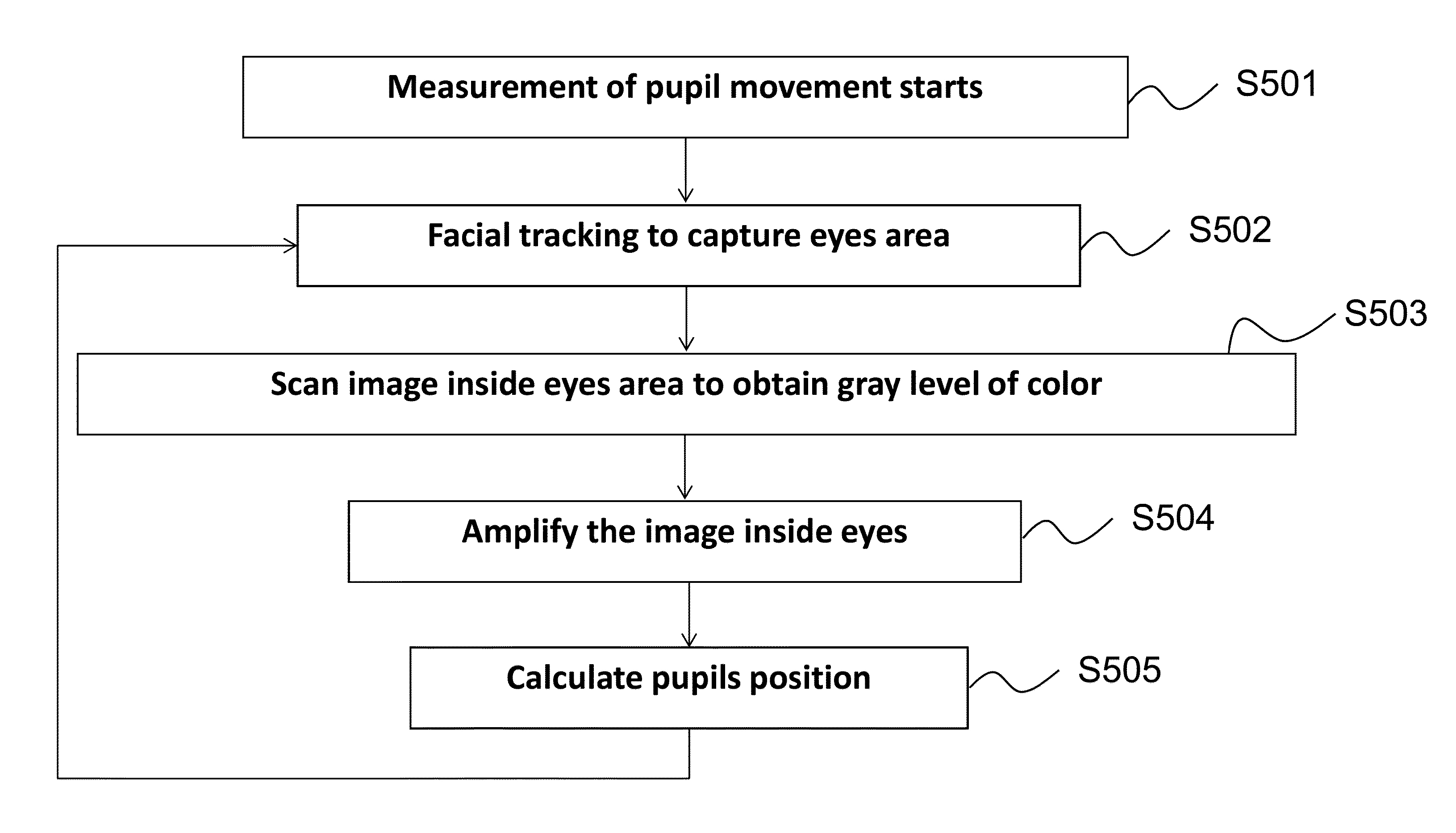
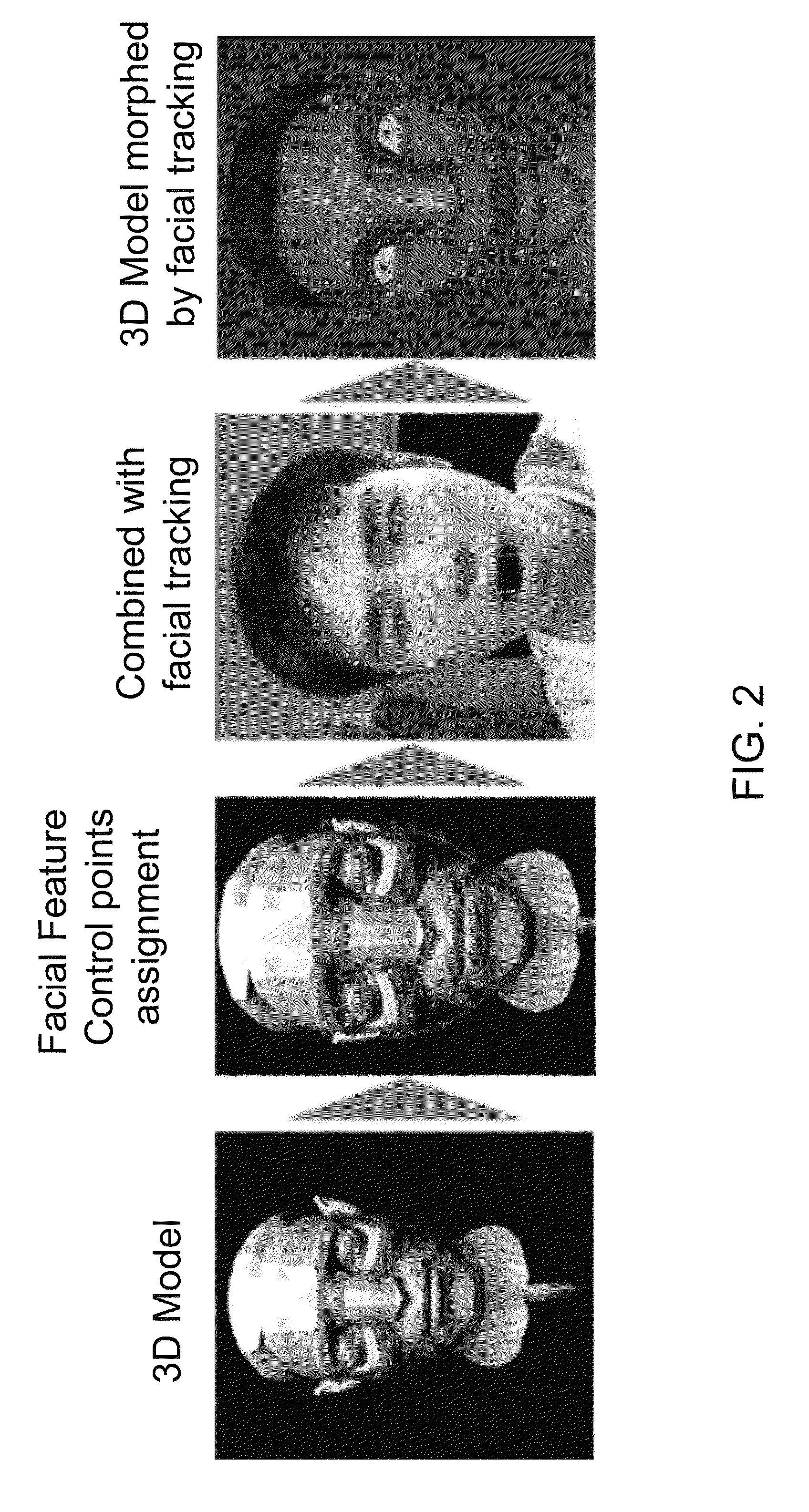
[0056]FIGS. 9 and 10 are diagrams illustrating a 3D model morphing method driven by real-time facial tracking according to the present invention. First, in step S401, real-time facial tracking is performed so as to output 66 facial feature tracking points on the person according to the facial tracking algorithm of the embodiment of present invention. Second, the configure file “A.config” is loaded in step S402. Finally, the driving points on the real-time 3D avatar facial image are controlled to move or change by the real-time movements of the tracking points performed by the person during real-time facial tracking in order to morph the 3D avatar facial image as shown in Step S403. FIG. 10 specifically illustrates pupil movement detection according to the embodiment of the present invention.

[0057]Referring to FIG. 14, a conceptual representation of the real-time 3D avatar image prior to morphing being subjected to the constraints of the facial feature control points and the boundary...


PUM


Abstract

A method of 3D morphing driven by facial tracking is provided. First, a 3D model is loaded. After that, facial feature control points and boundary control points are picked up respectively. A configure file “A.config” including the facial feature control points and boundary control points data that are picked up corresponding to the 3D avatar is saved. Facial tracking algorithm is started, and then “A.config” is loaded. After that, controlled morphing of a 3D avatar by facial tracking based on “A.config” is performed in real time by a deformation method having control points. Meanwhile, teeth and tongue tracking of the real-time face image, and scaling, translation and rotation of the real-time 3D avatar image is also provided. In addition, a control point reassignment and reconfiguration method, and a pupil movement detection method is also provided in the method of 3D morphing driven by facial tracking.

Description

BACKGROUND OF THE INVENTION[0001]1. Field of the Invention[0002]The present invention relates to a method of 3D model morphing, and more particularly, to a method of 3D model morphing driven by facial tracking, and an electronic device adopting the method of 3D model morphing driven by facial tracking.[0003]2. Description of the Prior Art[0004]Please refer to FIG. 1. FIG. 1 is a diagram showing a traditional 3D model morphing and motion capture technique. In FIG. 1, the traditional 3D model morphing and motion capturing that are commonly applied in commercial movies' visual effects usually use high speed camera to capture a large number of color-dot tags disposed on a subject or user (i.e. a whole person). These color-dot tags are typically pasted in advance on the subject or user's face to track facial expression. However, it's highly inconvenient and non-intuitive to paste such large number of color-dot tags on the face.[0005]Hence, how to improve the method of 3D morphing has bec...

Claims


Application Information

Patent Timeline
Patent Type & Authority Patents(United States)
IPC IPC(8): G06T19/20G06K9/00G06K9/46G06T7/20G06T13/40
CPCG06T19/20G06K9/00214G06K9/00228G06K9/4671G06T7/2046G06T13/40G06T2207/20101G06T2207/30201G06T2210/44G06T2219/2021G06T7/251G06V20/653G06V40/161G06V10/462G06F18/00
Inventor YE, ZHOULU, YING-KOHSU, YI-CHIAJENG, SHENG-WEN
Owner ULSEE
Why Eureka
Try Eureka