
Multiple effect concentration swap de-scaling system

a technology of concentration swap and desalination system, which is applied in water treatment multi-stage treatment, water treatment parameter control, specific water treatment objectives, etc., can solve the problems of no convenient way to dispose of brine reject, inland brackish water can be desalted, and the first two methods are becoming more difficult to use. , to achieve the effect of reducing scaling

Active Publication Date: 2016-02-23
SALTWORKS TECH INC
View PDF19 Cites 14 Cited by
  • Summary
  • Abstract
  • Description
  • Claims
  • Application Information

AI Technical Summary

Benefits of technology

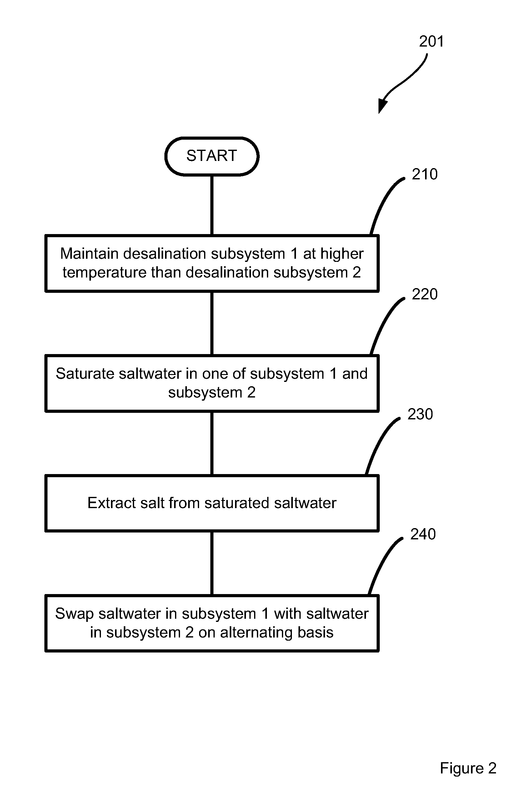
This patent describes a method to reduce scaling in a system that removes salt from saltwater. The method involves using two stages of desalination, with the first stage evaporating the saltwater at a higher temperature and condensing the product water, while the second stage evaporates the second saltwater at a lower temperature and condenses the product water. The two stages are then swapped, resulting in a smaller amount of scaling buildup in the system. The technical effect of this method is to improve the efficiency and lifespan of desalination systems.

Problems solved by technology

Inland brackish water can be desalted; however, there is often no convenient way to dispose of the brine reject.
The first two methods are becoming more challenging to use due to tightening environmental regulations and associated costs.
Despite their popularity, ZLD processes are expensive, costing roughly five times as much as employing traditional deep wells.
ZLD processes also experience considerable reliability challenges due to the inherent saturation point operation.
The capital costs of ZLD processes are high due to the extensive use of alloyed steels and titanium required at the operating temperatures and pressures.
Energy costs are high due to the use of large volume compressors, which on average consume 20 to 60 kWh of electrical-mechanical power per cubic meter treated.
However, saturated operation increases the propensity of solids and scale to build up on internal surfaces, reducing heat transfer effectiveness and clogging flow paths resulting in performance degradation and reliability challenges.

Method used


Image

  • Multiple effect concentration swap de-scaling system
  • Multiple effect concentration swap de-scaling system
  • Multiple effect concentration swap de-scaling system

Examples


Embodiment Construction

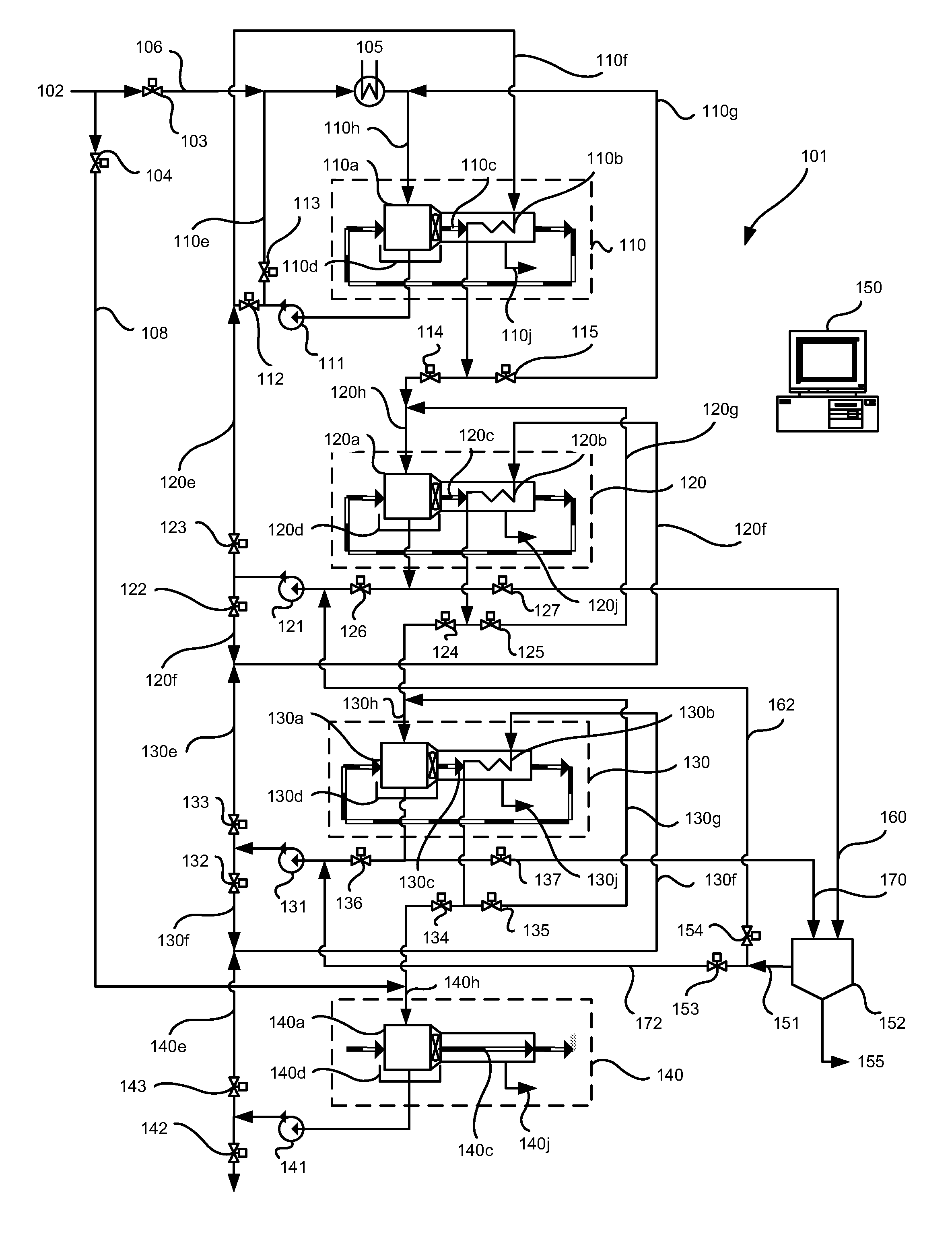
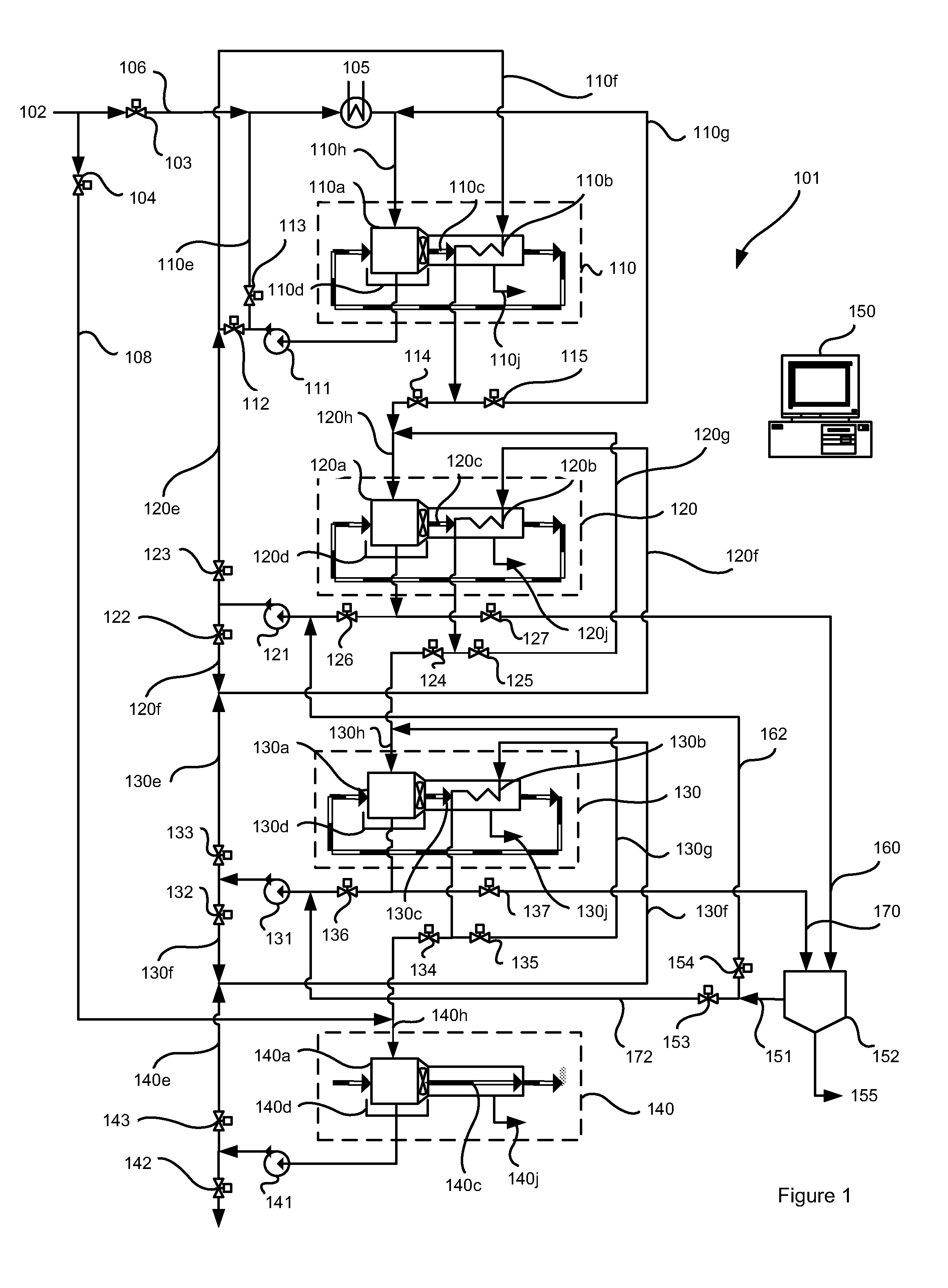
[0068]Embodiments described herein are directed to a multi-effect thermal desalination system arranged for changing the order in which physical thermal desalination subsystems are applied in a multi-effect thermal desalination system. The term “multi-effect thermal desalination system” is used herein to describe a thermal desalination system comprising more than one thermal desalination subsystem and therefore more than one associated desalination process stage. An example embodiment of the system and method disclosed herein is based on a multi-effect humidification dehumidification (HDH) thermal desalination system. At least some of the embodiments described herein are directed to reducing the frequency of or need for washing the desalination system, and to mitigating the negative consequences of adding freshwater to a solution being concentrated.

[0069]FIG. 1 shows a first example embodiment of a four stage multi-effect HDH thermal desalination system 101, comprising first through ...


PUM

PropertyMeasurementUnit
temperatureaaaaaaaaaa
concentrationaaaaaaaaaa

Abstract

A multistage thermal desalination system, together with its associated method of use, allows de-scaling of subsystems exposed to saturated saltwater by alternating the saturation stage of the process between two neighboring physical desalination stages. The desalination system is provided with at least one transfer conduit, at least one pump, and valving to permit saltwaters being desalinated by higher and lower stage desalination subsystems to be swapped. By replacing the saturated saltwater in a higher salt concentration desalination subsystem with lower salt concentration saltwater, the scaling in higher salt concentration desalination subsystem is reduced while the saturation load is placed on another of the desalination subsystems.

Description

CROSS-REFERENCE TO RELATED APPLICATIONS[0001]This application is a US National Stage of International Application No. PCT / CA2014 / 051134, filed 26 Nov. 2014, which claims the benefit of U.S. Provisional Patent Application No. 61 / 909,288, filed 26 Nov. 2013, each herein fully incorporated by reference.TECHNICAL FIELD[0002]The present disclosure provides a method to improve the reliability of multiple effect evaporation or flash desalination processes. More specifically, the method periodically swaps the concentration of the saltwater processed in each effect to enable de-scaling during operation.BACKGROUND[0003]Treatment of waste saltwater to reduce volume is becoming increasingly important, particularly for mining, oil and gas, and inland desalination systems. Mines can produce tailings water, which is typically ponded. Oil and gas operations can produce saltwater within the hydrocarbon reserve or during processing. Desalination is increasingly being used in both industries as regula...

Claims


Application Information

Patent Timeline
Patent Type & Authority Patents(United States)
IPC IPC(8): C02F1/04B01D3/06B01D3/14C02F1/26C02F1/06B01D3/42B01D5/00C02F1/00C02F103/08C02F103/10
CPCC02F1/06B01D3/065B01D3/143B01D3/146B01D3/42B01D5/0036C02F1/008C02F1/042C02F1/265C02F2103/08C02F2103/10C02F2209/005C02F2209/03C02F2209/05C02F2209/40C02F2301/08C02F1/04C02F2209/006C02F2303/22B01D1/26Y02A20/124Y02A20/131
Inventor SPARROW, BENJAMIN STUARTNAVEED, SAQIB
Owner SALTWORKS TECH INC
Learn More