Lighting device having LED elements
a technology of led elements and lighting devices, which is applied in the direction of semiconductor devices for light sources, light and heating apparatus, fixed installations, etc., can solve the problems of difficult to use a device of this kind as an ordinary lighting device, complicated and difficulty in simple structure of straight tube lighting systems. to achieve the effect of increasing hea
- Summary
- Abstract
- Description
- Claims
- Application Information
AI Technical Summary
Benefits of technology
Problems solved by technology
Method used
Image
Examples
embodiment 1
[0197]If the bias current 41 is not fed, the LED element 252 does not emit light during the interruption period of the LED primary current; accordingly the light of the lighting device 200 greatly flickers. However, the bias current 4 flows the LED bias current 41 through the LED group 250, which prevents lighting-cease of the LED elements 252 although their amount of light emission lowers. Thereby, the light flicker of the lighting device 200 can be significantly improved. The bias current 4 is very small compared to the primary current 2. The value of the bias current 4 is one-tenth or less of the peak value of the primary current 2 for example, which allows maintaining the cooling effect on the LED element 252 during the cooling period. Providing in this way the bias current feeding circuit 700 can suppress the temperature rise of the LED element 252 and, further, can improve the light flicker of the lighting device 200.[0198]11. Embodiment 1 of a specific example of the bias cur...
embodiment 2
[0221]The graph 16 describes the variation of the bias current 4 at the beginning time point T1 and T2 of the period P2 and the graph 17 describes the variation of the bias current 4 at the ending time point T3 and T4 of the period P2. A consideration should be given to the minimum value of the bias current 4; a capacitance of 1 μF to 10 μF is preferable. The difference between the graph 16 and the graph 17 is very big. Although the behavior shows a big difference like that, the above-stated configuration still can contributes to the prevention of the flickering on a lighting device and further offers a large effect for the prevention of the heat generation.[0222]12. Explanation of other embodiments[0223]12.1 Explanation of the embodiment 2 as another embodiment of the embodiment given in FIG. 1
[0224]As described in FIG. 33, the difference between the current value of the bias current 4 at the beginning time points T1 and T2 of the period P2 and the current value of the bias current...
embodiment 3
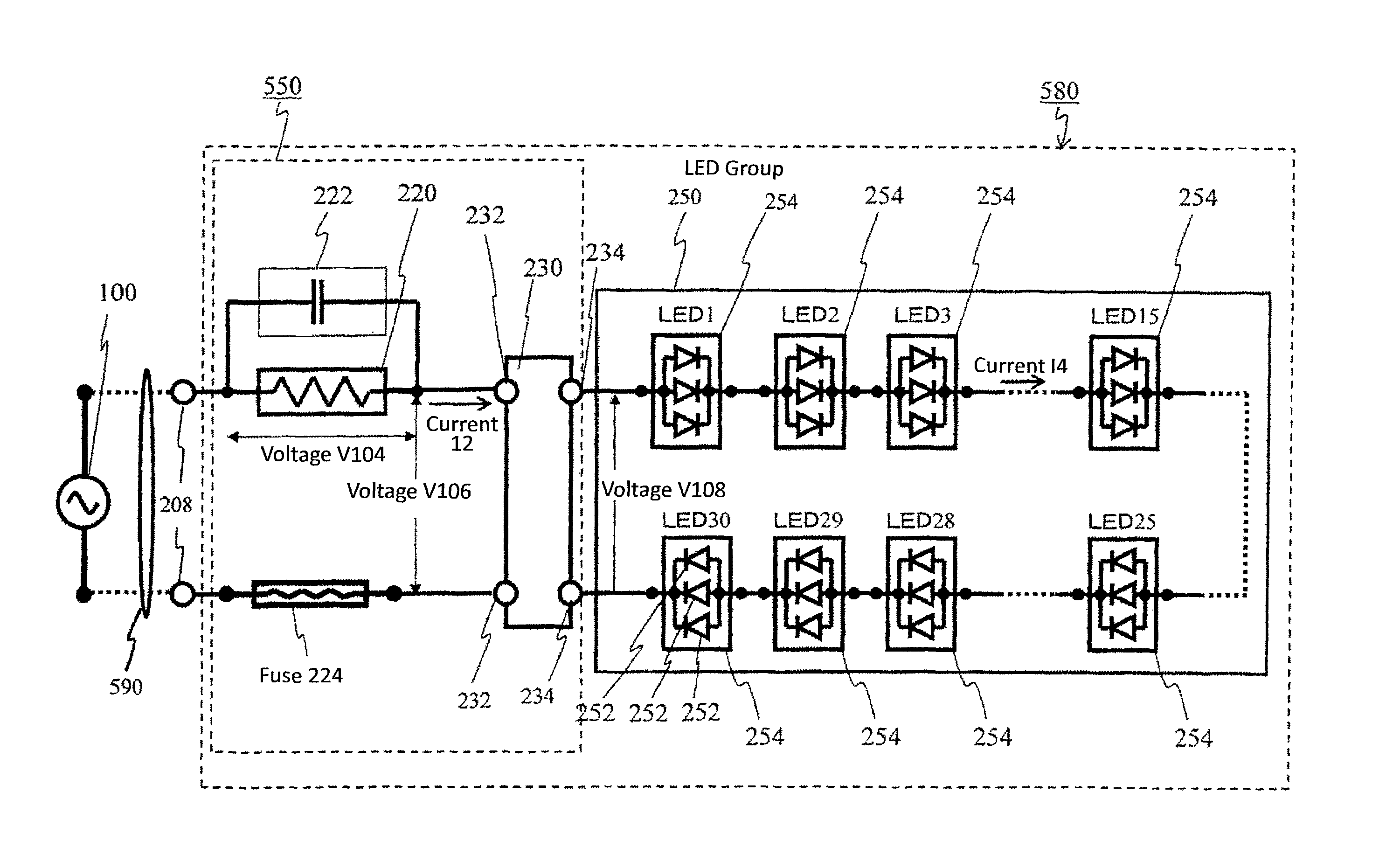
[0228]FIG. 35 illustrates further another embodiment (hereinafter referred to as the embodiment 3). In this embodiment likewise as in the other embodiment, the primary current feeding circuit 104 has the parallel circuit 110 having the primary current capacitor 222 and the resistor 220, and the rectification circuit 230 having the input terminal 232 and the output terminal 234. An alternating current is fed to the input terminal 232 of the rectification circuit 230 through the primary current capacitor 222. The alternating current so fed is rectified into the primary current 2 of pulsating current, which is then fed from the output terminal 234 of the rectification circuit 230 to the LED group 250.
[0229]The difference from the embodiment 1 or the embodiment 2 is that the charging current 12 of the bias capacitor 720 in the bias current feeding circuit 700 is fed not from the output side of the primary current feeding circuit 104 but from the power source side of the primary current ...
PUM
 Abstract
Description
Claims
Application Information
 - R&D
- Intellectual Property
- Life Sciences
- Materials
- Tech Scout
- Unparalleled Data Quality
- Higher Quality Content
- 60% Fewer Hallucinations
Browse by: Latest US Patents, China's latest patents, Technical Efficacy Thesaurus, Application Domain, Technology Topic, Popular Technical Reports.
© 2025 PatSnap. All rights reserved.Legal|Privacy policy|Modern Slavery Act Transparency Statement|Sitemap|About US| Contact US: help@patsnap.com


