
Method for detecting a wet road

a technology for detecting roads and roads, applied in the direction of vehicle position/course/altitude control, process and machine control, instruments, etc., can solve the problems of complex system, high cost, and general response to rain, and achieve comparatively easy and inexpensive implementation, less moisture, and less speed

Active Publication Date: 2016-03-01
ROBERT BOSCH GMBH
View PDF27 Cites 22 Cited by
  • Summary
  • Abstract
  • Description
  • Claims
  • Application Information

AI Technical Summary

Benefits of technology

This approach provides reliable detection of road wetness, enabling adaptive control of vehicle components, improving safety and reducing costs by leveraging existing camera technology, and enhancing the responsiveness of systems like ABS and ESP to wet road conditions.

Problems solved by technology

However, the rain sensor described above has the disadvantage that it generally responds only to rain.
Such a sensor may be used to control the windshield wiper but it can hardly be used appropriately to control other components of the vehicle in which an adaptation to moisture in the surroundings of a vehicle would be meaningful.
However such a system is complex and is therefore expensive.
An adjustment of a highly developed ABS or ESP in adjustment to the wet road surface based on data from one rain sensor is therefore impossible.

Method used


Image

  • Method for detecting a wet road
  • Method for detecting a wet road
  • Method for detecting a wet road

Examples


Embodiment Construction

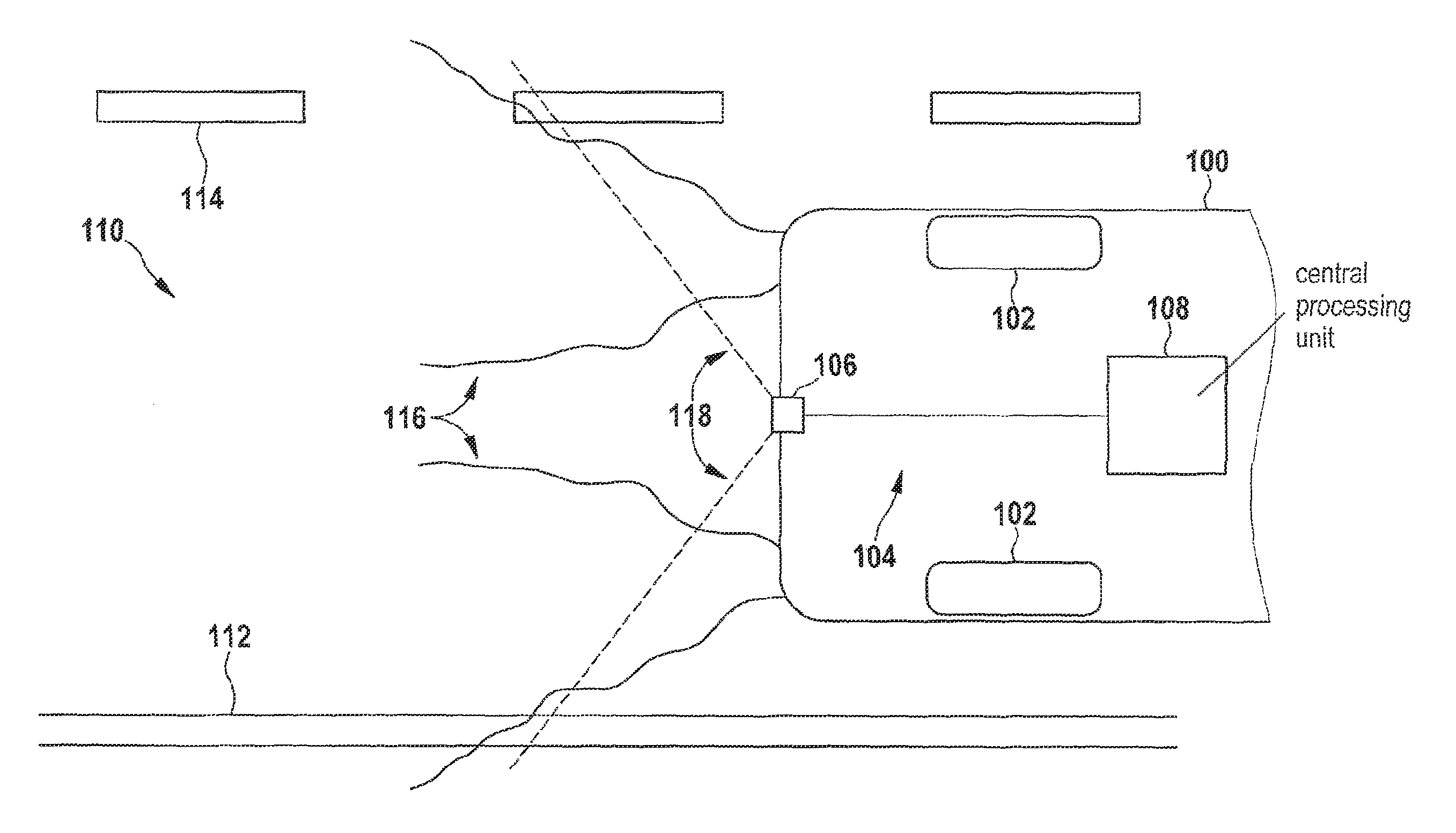
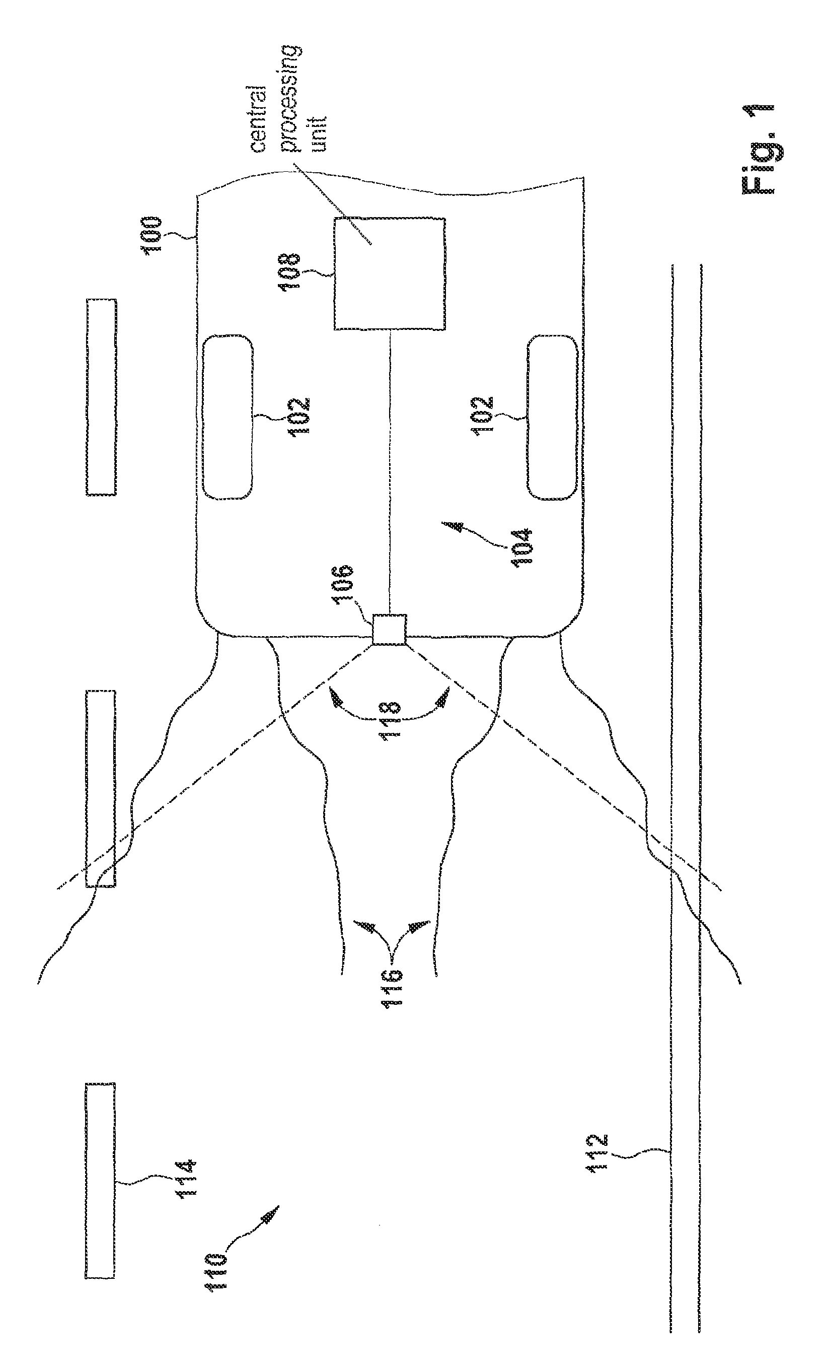
[0025]FIG. 1 shows the rear end of a vehicle 100 having rear wheels 102 indicated schematically. Vehicle 100 is equipped with a driver assistance system 104 designed according to the present invention which includes, among other things, a rearview camera 106 and a central processing unit 108, which is implemented as an ECU (electronic control unit). Vehicle 100 travels on a road surface 110, which is indicated by a side border 112 and lane markings 114. Each rear wheel 102 of vehicle 100 produces a spray trail 116 due to the wetness on road surface 110, the parts of this spray trail being detected in the field of vision 118 of rearview camera 106.

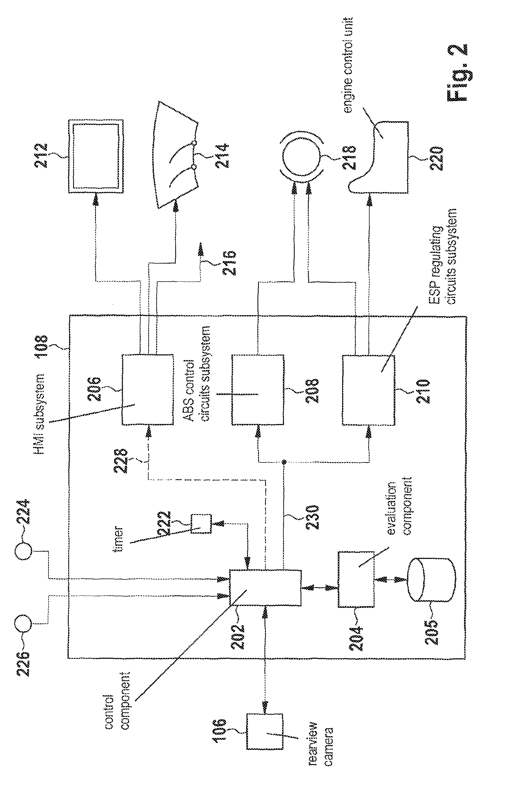
[0026]In FIG. 2, functional components of ECU 108 of driver assistance system 104 are indicated. ECU 108 includes a control component 202, an evaluation component 204 and subsystems 206, 208 and 210. In the example shown in FIG. 2, subsystem 206 controls an HMI (human-machine interface) in the form of a display 212, windshield wipers 214 as...


PUM


Abstract

Methods in a driver assistance system of a vehicle for detecting wetness on a road surface as well as a corresponding driver assistance system having a rearview camera are described. The method may include the following: recording an image of an area located behind the rear end of the vehicle, using the rearview camera; evaluating the recorded image for the presence of a spray trail caused by the vehicle; and selectively outputting, based on the evaluation, a wetness signal for triggering an automatic response by the driver assistance system to the wet road surface.

Description

FIELD[0001]The present invention relates to a method in a driver assistance system of a vehicle for detecting wetness on a road surface as well as a corresponding driver assistance system.BACKGROUND INFORMATION[0002]A driver assistance system provides one or multiple accessory equipment items in a vehicle to support the driver in certain driving situations. Such additional equipment includes, for example, an ABS (antilock brake system), an ESP (electronic stability program), an ACC (adaptive cruise control) or a parking assistance system.[0003]The use of a rain sensor for automatic activation of the windshield wipers of a vehicle when it is raining belongs to the area of driver assistance. In this regard, German Patent No. DE 103 16 794 A1 describes a rain sensor which includes a camera. The camera is directed from the interior at an object fixedly mounted on the vehicle in front of the windshield, for example, the hood of the vehicle. The image recorded by the camera is compared wi...

Claims


Application Information

Patent Timeline
Patent Type & Authority Patents(United States)
IPC IPC(8): B60W40/06B60Q1/08G06K9/00B60R16/023
CPCB60R16/0237B60Q1/085G06K9/00791B60Q2300/312G06V20/56
Inventor HEGER, THOMASHELMLE, MICHAEL
Owner ROBERT BOSCH GMBH
Learn More