

Rotatable heating member and image heating apparatus
a heating member and rotating technology, applied in the direction of electrographic process apparatus, instruments, optics, etc., can solve the problem of unfavorable output image glossiness and other problems
- Summary
- Abstract
- Description
- Claims
- Application Information
AI Technical Summary
Benefits of technology
Problems solved by technology
Method used
Image

Examples
first embodiment
Effect of First Embodiment
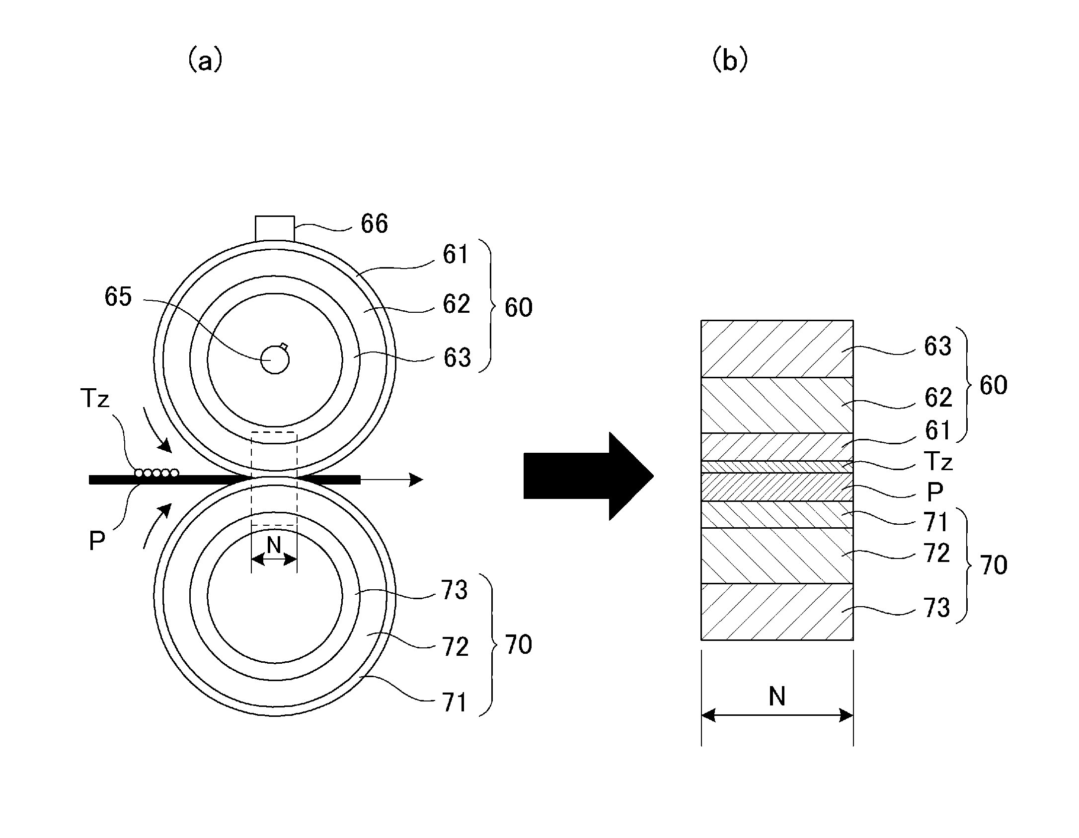
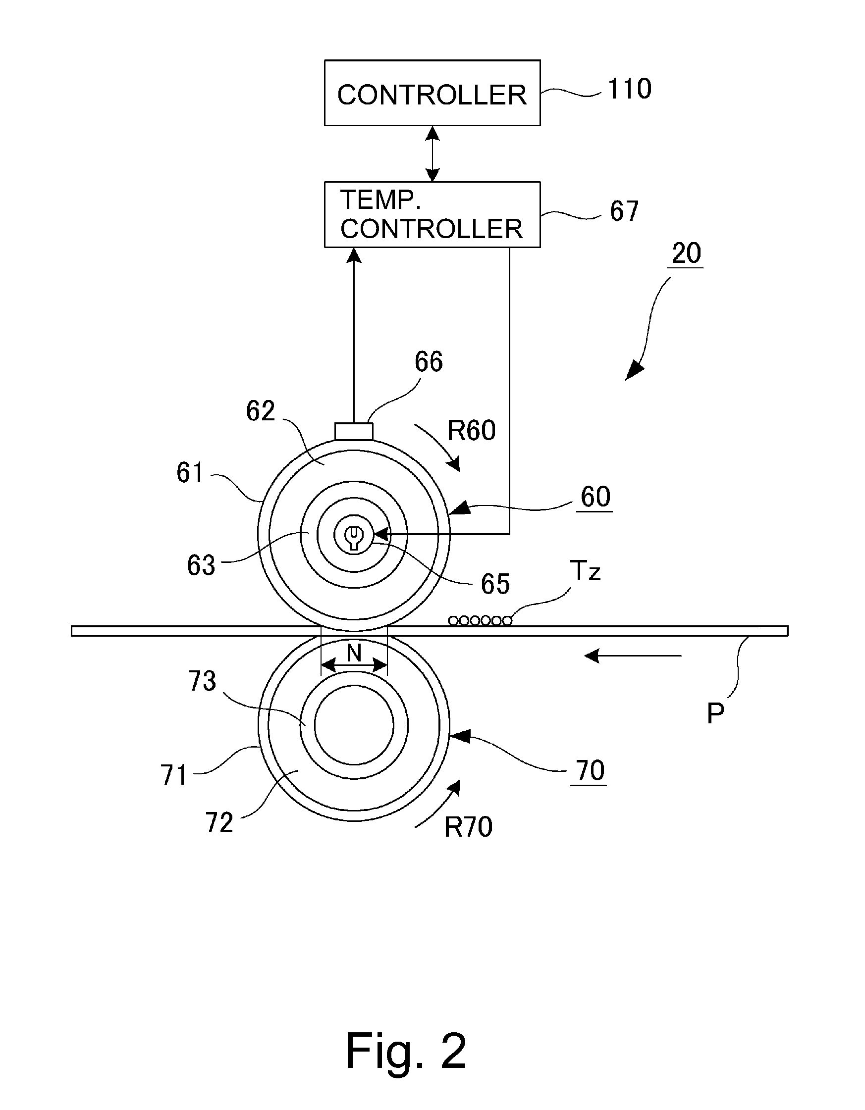
[0083]In First Embodiment, when the thermal effusivity of the parting layer 61 is Bs, and the thermal effusivity of the elastic layer 62 is Be, Be=Bs, i.e., −0.04<(Be−Bs) / Be<0.04 is satisfied. For this reason, even when a variation in thickness of the parting layer for each of places at the surface of the fixing roller becomes large with accumulation of the image formation, a variation in fixing property is suppressed at the entire surface, so that the uneven glossiness and a partial lowering in image intensity do not readily generate.
[0084]That is, in view of the change in thickness of the outermost layer generated due to the manufacturing step or durable deterioration during use, the parting layer 61 of the fixing roller 60 is designed so that the thickness thereof is increased to some extent. In First Embodiment, the thermal effusivity of the elastic layer 62 and the thermal effusivity of the parting layer 61 are made equal to each other, and therefore e...
modified embodiment 1
[0087]As shown in (a) of FIG. 3, the silicone rubber of the elastic layer 62 needs to have a high heat-conductive property, in addition to softness, in order to conduct heat from an inside heat source to an outside. For that reason, into the silicone rubber, as the filler, SiC, ZnO, Al2O3, AlN, MgO, SiO2, carbon black or the like is added. These substances may also be added in mixture of several species.
[0088]However, the filler in the elastic layer 62 has the thermal conductivity which is several times to several tens of times the thermal conductivity of the silicone rubber, and therefore in some cases, the uneven glossiness is caused on the toner after the fixing. In order to solve this problem, the uneven glossiness may also be suppressed by providing a density distribution in the thickness direction to lower the thermal conductivity in a shallow region of the elastic layer 62 in the parting layer 61 side.
[0089]In order to enhance the thermal conductivity by increasing the therma...
modified embodiment 2
[0090]FIG. 8 is an illustration of a structure of a fixing roller in Modified Embodiment 2. As shown in FIG. 8, in the case where the thermal effusivity Bs is controlled by adding the filler into the fluorine-containing resin material used for the parting layer 61, when the addition amount of the filler is increased, there is a possibility that the parting property with respect to the melted toner on the surface of the parting layer 61 lowers. In this case, it is possible to use a law such that repellency on the surface of a substance is determined by a property in a range of several 10 nm from a material surface.
[0091]That is, the surface layer in the range of several 10 nm from the surface of the parting layer 61 is constituted as a first parting layer 61a formed only of the fluorine-containing resin material containing no filler, and under the first parting layer 61a, a second parting layer 61b formed of the fluorine-containing resin material in which the filler contained at a hi...
PUM
 Abstract
Description
Claims
Application Information