Driving method of field sequential liquid crystal display device
a liquid crystal display device and sequential technology, applied in the direction of instruments, computing, electric digital data processing, etc., can solve the problems of loss of continuity of display data in consecutive frames, lack of given display data, etc., to suppress changes (deterioration) of display, increase the input frequency of image signals, and increase the frame frequency of liquid crystal display devices
- Summary
- Abstract
- Description
- Claims
- Application Information
AI Technical Summary
Benefits of technology
Problems solved by technology
Method used
Image
Examples
modification example
[0096]The liquid crystal display device described above is one embodiment of the present invention, and the present invention includes a liquid crystal display device which is different from the above-described liquid crystal display device.
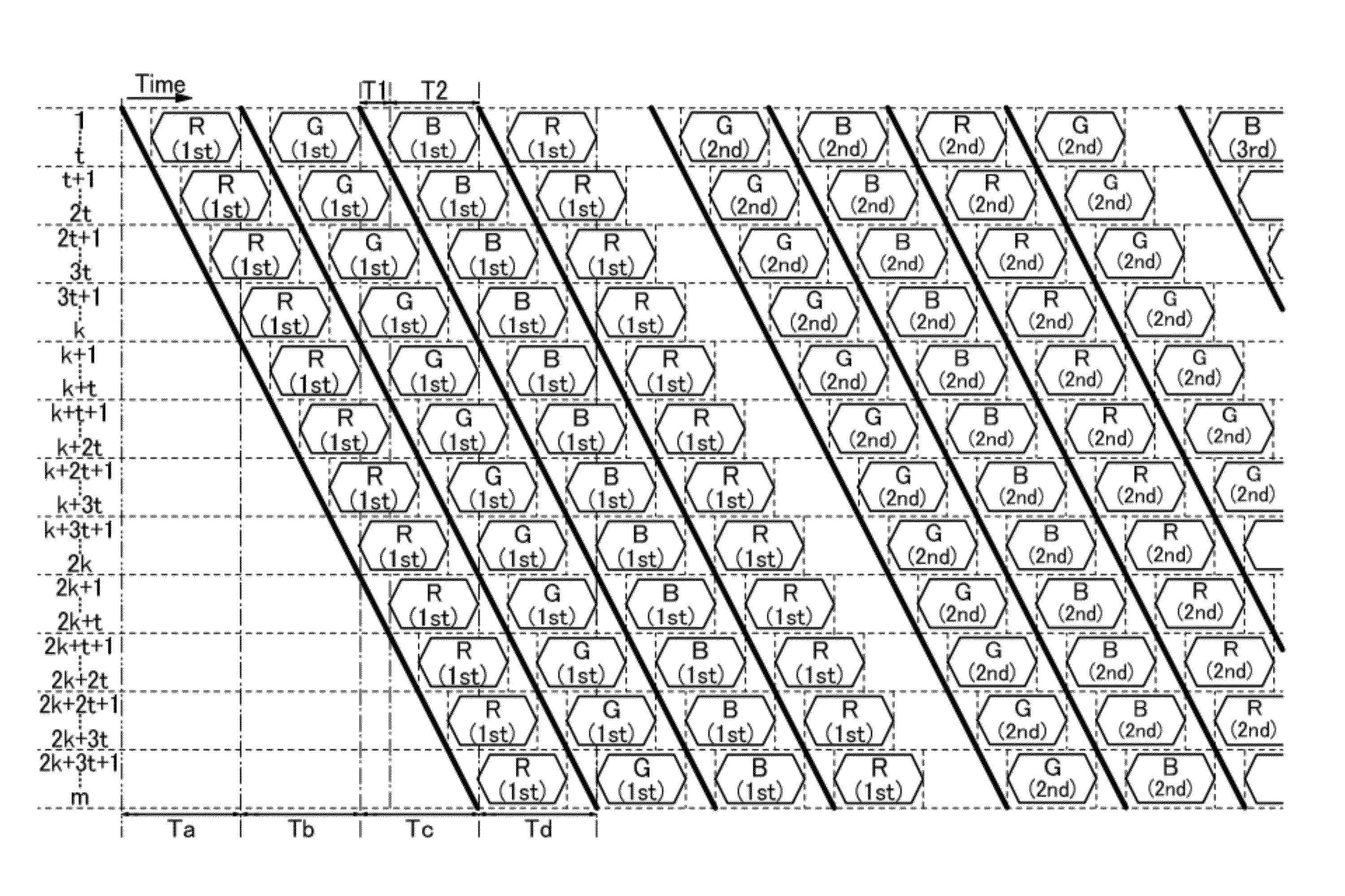
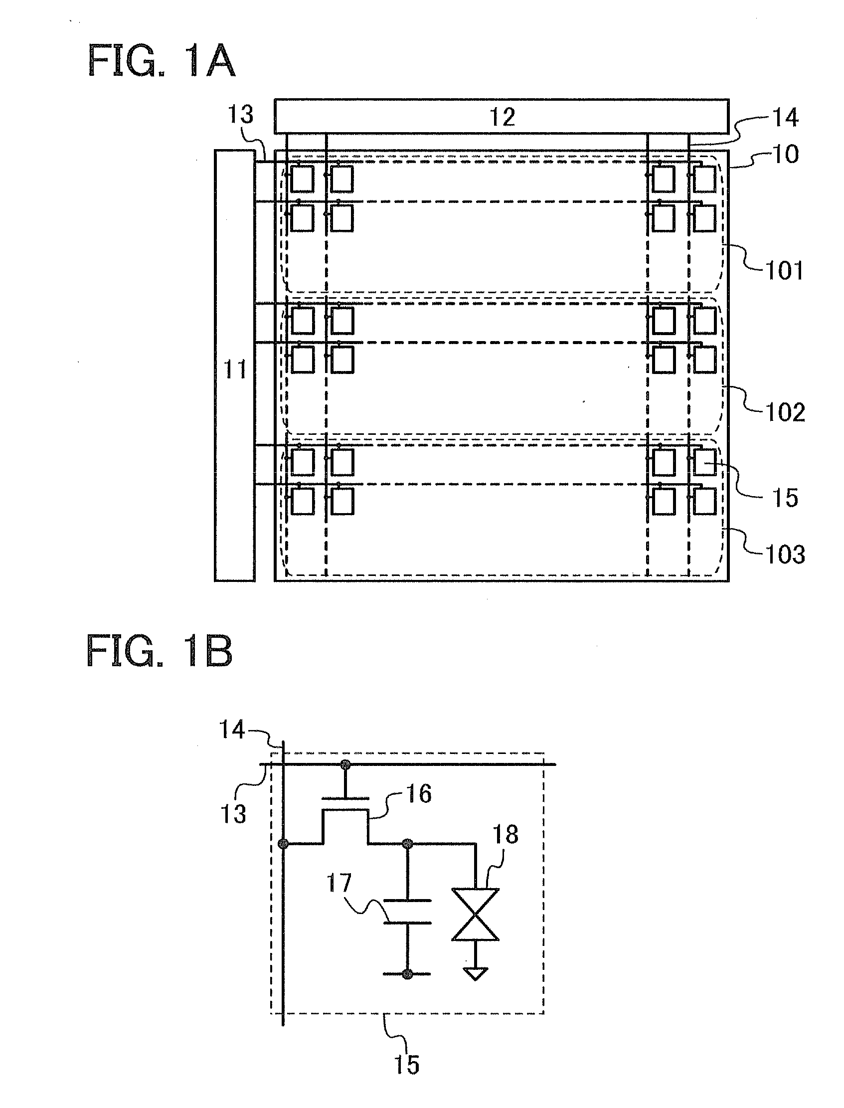
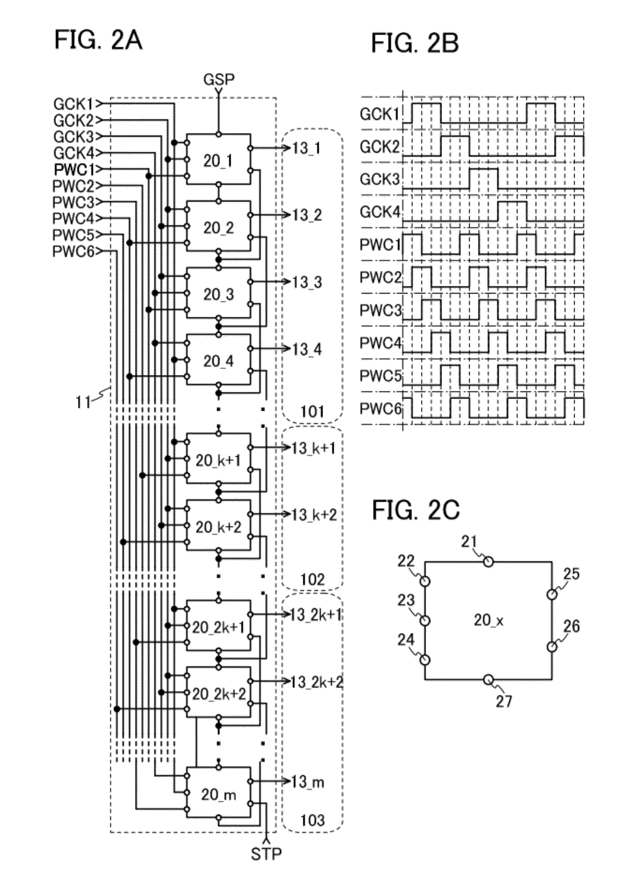
[0097]For example, the liquid crystal display device described above has a structure in which the pixel portion 10 is divided into three regions and the image signals are supplied concurrently to the three regions; however, a liquid crystal display device according to one embodiment of the present invention is not limited to the structure. In other words, the liquid crystal display device according to one embodiment of the present invention can have a structure in which the pixel portion 10 is divided into a plurality of regions the number of which is not three and the image signals are supplied concurrently to the respective plurality of regions. In the case where the number of regions is changed, it is necessary to set clock signals for the sca...
specific example
[0110]A specific example of the above-described liquid crystal display device will be described below.
[0111]FIG. 12A is a top view of a structure example of a pixel of the above-described liquid crystal display device, and FIG. 12B is a cross-sectional view taken along line A-A′ and line B-B′ in FIG. 12A.
[0112]The pixel illustrated in FIG. 12A includes a scan line 801, a signal line 802, a common potential line 803, a capacitor line 804, a transistor 805, a pixel electrode 806, a common electrode 807, and a capacitor 808. In addition, these components are formed using a first conductive layer 851, a semiconductor layer 852, a second conductive layer 853, and a third conductive layer 854 (also referred to as a transparent electrode layer) each of which is obtained in such a way that a thin film formed over the entire surface of a substrate is separated and processed into a plurality of layers.
[0113]Specifically, the scan line 801, a gate electrode of the transistor 805, and one elect...
PUM
 Abstract
Description
Claims
Application Information
 - R&D
- Intellectual Property
- Life Sciences
- Materials
- Tech Scout
- Unparalleled Data Quality
- Higher Quality Content
- 60% Fewer Hallucinations
Browse by: Latest US Patents, China's latest patents, Technical Efficacy Thesaurus, Application Domain, Technology Topic, Popular Technical Reports.
© 2025 PatSnap. All rights reserved.Legal|Privacy policy|Modern Slavery Act Transparency Statement|Sitemap|About US| Contact US: help@patsnap.com


