Eureka AIR delivers breakthrough ideas for toughest innovation challenges, trusted by R&D personnel around the world.

Infrared sensor

Active Publication Date: 2016-03-08
MITSUBISHI MATERIALS CORP
View PDF21 Cites 2 Cited by
  • Summary
  • Abstract
  • Description
  • Claims
  • Application Information

AI Technical Summary

Benefits of technology

The present invention provides an infrared sensor that can be mounted easily and in a small space while still being high-density packaged. It includes a reinforcing plate and terminal electrodes that can be connected to an external connector. The sensor is designed to perform well in high-density packaging.

Problems solved by technology

In the method, the temperature of a measurement object such as a device or the like is indirectly detected, resulting in an increase in detection errors and difficulty in highly accurate detection.
However, the resin film containing an infrared absorbing material exhibits high heat conductivity and thus it becomes difficult to cause the temperature difference between the heat sensitive element for infrared detection and the heat sensitive element for temperature compensation.
In addition, in order to increase the temperature difference between these heat sensitive elements, the distance between these heat sensitive elements needs to be spaced apart from each other, resulting in an increase in the overall shape of the infrared sensor and a difficulty in achieving size reduction of the same.
Furthermore, the structure for shielding the heat sensitive element for temperature compensation from light needs to be provided on the case itself, which makes the infrared sensor more expensive.
In Patent Document 2, the frame body having excellent heat conductivity is employed, and thus, heat supplied from the infrared absorbing film is also dissipated, resulting in degradation in sensitivity.
Furthermore, although the infrared sensor disclosed in Patent Document 2 employs a structure in which one of the heat sensitive elements is shielded from infrared radiation with the housing, the shielding portion of the case which only blocks infrared radiation absorbs infrared radiation, resulting in changes in the temperature of the shielding portion.
Consequently, the heat sensitive element for temperature compensation is inappropriate for use as a reference.

Method used


Image

  • Infrared sensor
  • Infrared sensor
  • Infrared sensor

Examples


first embodiment

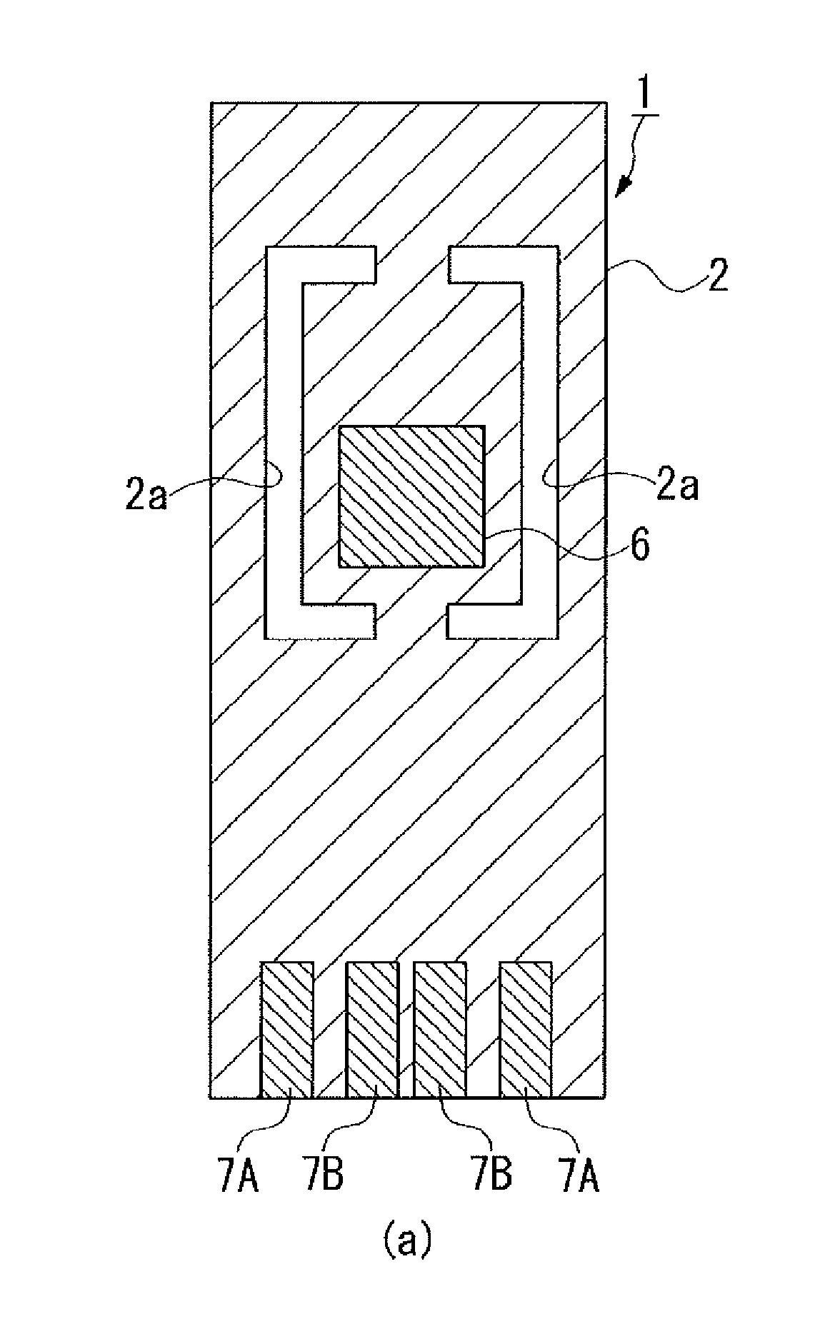
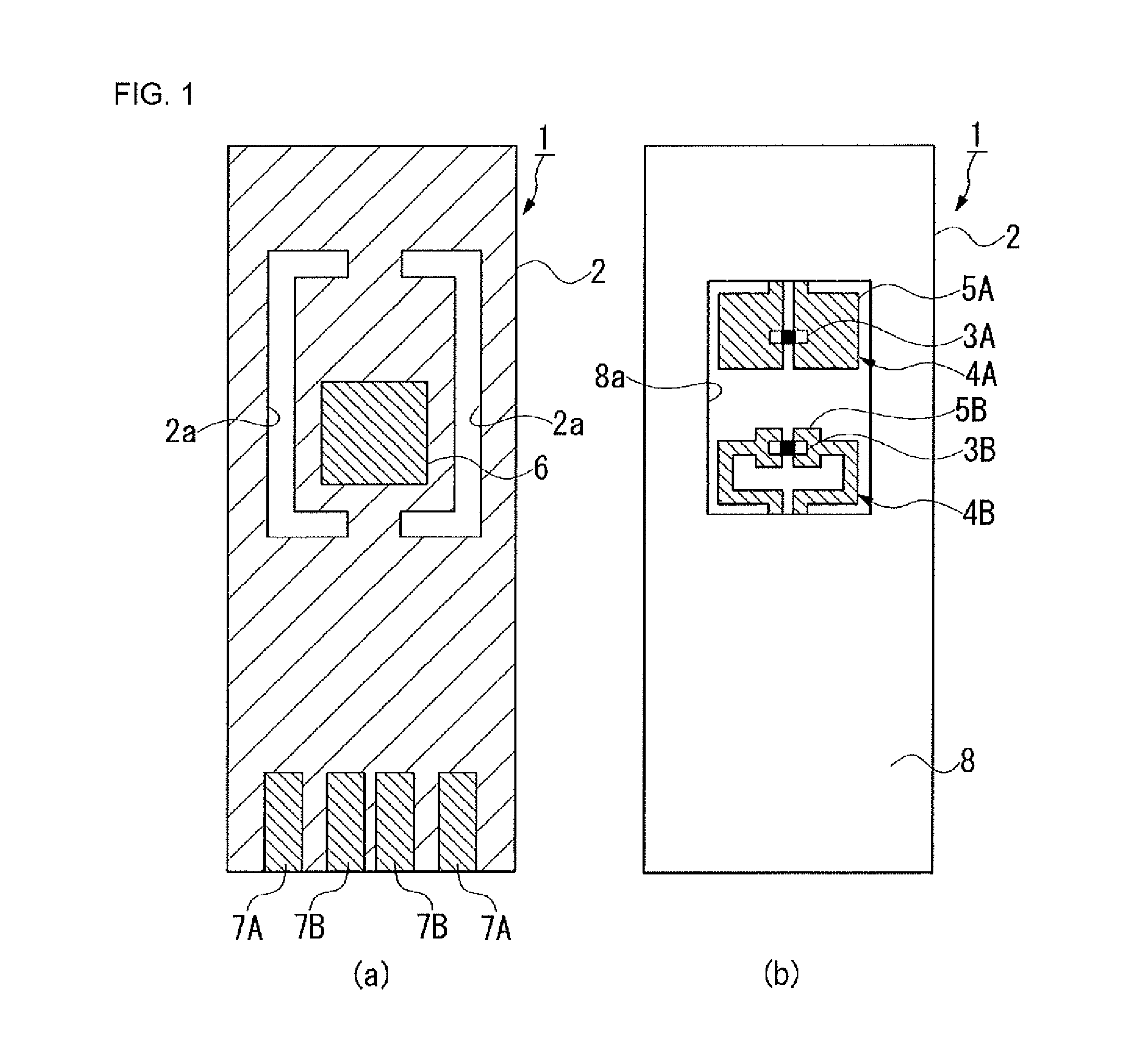
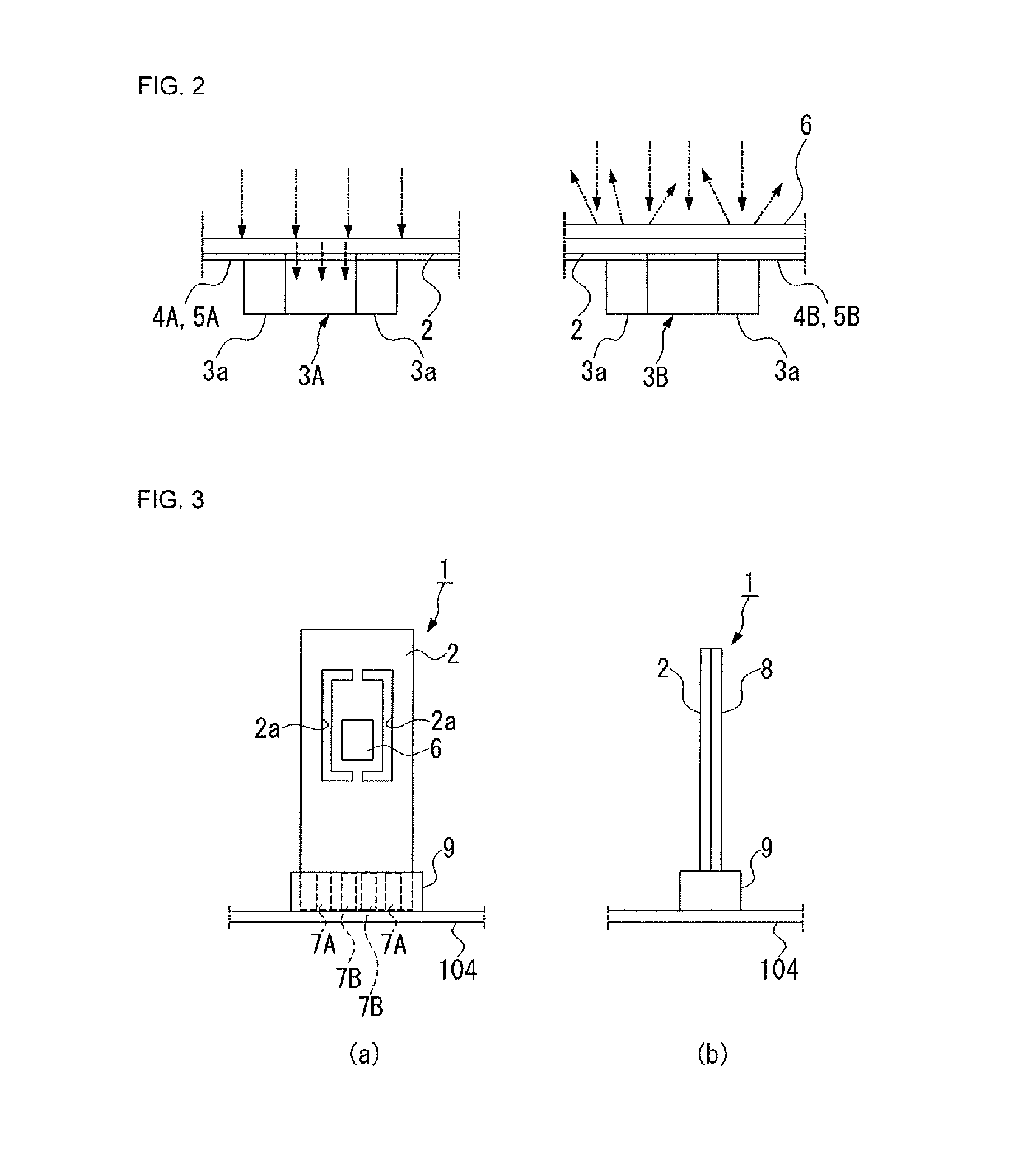
[0045]Hereinafter, a description will be given of an infrared sensor according to the present invention with reference to FIGS. 1 to 5. In the drawings used in the following description, the scale of each component is changed as appropriate so that each component is recognizable or is readily recognized.

[0046]As shown in FIGS. 1 to 4, the infrared sensor (1) of the present embodiment includes an insulating film (2); a first heat sensitive element (3A) and a second heat sensitive element (3B) that are disposed on one surface of the insulating film (2) so as to be separated apart from one another; a pair of first conductive wiring films (4A) serving as conductive metal films that are formed on one surface of the insulating film (2) and are connected to the first heat sensitive element (3A) and a pair of second conductive wiring films (4B) serving as conductive metal films that are connected to the second heat sensitive element (3B); an infrared reflection film (6) that is disposed on ...

second embodiment

[0065]Next, a description will be given below of an infrared sensor according to the present invention with reference to FIG. 6. In the description of the following embodiment, the same components described in the above embodiment are designated by the same reference numerals and a duplicated explanation will be omitted.

[0066]The second embodiment differs from the first embodiment in that, while only one sensor part having the first heat sensitive element (3A) and the second heat sensitive element (3B) is provided on the insulating film (2) in the first embodiment, the infrared sensor (21) of the second embodiment is integrally provided with not only the sensor part but also the circuit part (22) which is a detection circuit for sensor control connected to the sensor part on the insulating film (2) as shown in FIG. 6.

[0067]The second embodiment also differs from the first embodiment in that a circuit part window (28b) of rectangular shape corresponding to the circuit part (22) is fo...


PUM


Abstract

A lightweight infrared sensor which is readily and stably erected to a substrate, the infrared sensor includes an insulating film; a first and second heat sensitive element are disposed on one surface of the insulating film separately; a first and second conductive film on one surface of the insulating film and are respectively connected to the first and the second heat sensitive element; an infrared reflection film on the other surface of the insulating film so as to face the second heat sensitive element; a reinforcing plate on which a sensor part window corresponding to a sensor part is formed and which is adhered to the insulating film; and a first and a second terminal electrode are respectively connected to the first and the second wiring film and formed on the edge of the insulating film.

Description

CROSS-REFERENCE TO RELATED APPLICATIONS[0001]This application is a U.S. National stage application of PCT International Application No. PCT / JP2012 / 001916 filed Mar. 21, 2012, which claims the benefit of Japanese Patent Application No. 2011-076767 filed Mar. 30, 2011, the entire contents of the aforementioned applications are hereby incorporated herein by reference.BACKGROUND OF THE INVENTION[0002]1. Field of the Invention[0003]The present invention relates to an infrared sensor that detects infrared radiation from a measurement object to thereby measure the temperature or the like of the measurement object.[0004]2. Description of the Related Art[0005]When the heat generation state of an electronic component (device) on a circuit substrate, such as a switching element such as FET, an electrolytic capacitor, or the like, is detected, there has been known a method in which a temperature sensor is provided on a circuit substrate in the vicinity of the device or a temperature sensor is p...

Claims


Application Information

Patent Timeline
IPC IPC(8): G01J5/02G01J5/20G01J5/10G01J5/06H01L37/02
CPCG01J5/10G01J5/0215G01J5/20G01J2005/067H01L37/02G01J5/068H10N15/10G01J5/02
Inventor NAKAMURA, KENZOISHIKAWA, MOTOTAKAUOZUMI, GAKUJI
Owner MITSUBISHI MATERIALS CORP
Why Eureka
Eureka Blog
Learn More