Adaptation of a 3D-surface model to boundaries of an anatomical structure in a 3D-image data set

a 3d surface model and data set technology, applied in image enhancement, image analysis, instruments, etc., can solve the problems of user requirements, time-consuming methods, and costly acquisition of magnetic resonance tomography images, and achieve the effect of facilitating the adaptation

Active Publication Date: 2016-03-08
TOMTEC IMAGING SYST
View PDF11 Cites 0 Cited by
  • Summary
  • Abstract
  • Description
  • Claims
  • Application Information

AI Technical Summary

Benefits of technology

[0028]The predefined angle, which is established by the second, third and occasionally fourth viewing plane with the characteristic plane, preferably is between 70° and 110°, especially preferred between 80° and 100°, especially 90°. In that the viewing planes 2 to 4 are always perpendicular to the characteristic plane (in the case of the right ventricle preferably the plane of symmetry) it is assured that the represented short axis views of the ventricle are as optimal as possible, wherein in turn the marker to be refined may be adapted with greater ease without errors.

Problems solved by technology

However, this method is time consuming and furthermore requires acquisition of costly magnetic resonance tomography (MRT) images.
The disadvantage with this process however resides in that the user is required to select sectional planes which he is not familiar with, especially the coronal plane.
By doing this errors will readily arise, which are not easily realized by the user.
The disadvantage of this process however resides in that the user has to find the anatomical positions corresponding to the land marks via an appropriate navigation across the acquired ultra sound images, in order to be able to place the land marks.
This occasionally may not be easy.
Both requirements collectively will strongly limit the selection of useful land marks.

Method used


Image

  • Adaptation of a 3D-surface model to boundaries of an anatomical structure in a 3D-image data set
  • Adaptation of a 3D-surface model to boundaries of an anatomical structure in a 3D-image data set
  • Adaptation of a 3D-surface model to boundaries of an anatomical structure in a 3D-image data set

Examples


Embodiment Construction

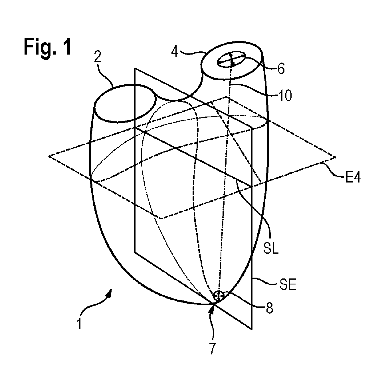
[0047]For the sake of improved orientation FIG. 1 shows a schematic drawing of a right ventricle 1. The latter generally is nestled to the larger left ventricle thus showing a relatively complex bag-like shape. The pulmonic valve 2 and the tricuspidal valve 4 can be seen basally, the apex which is referred to as 7 can be seen apically. The right ventricle 1 approximately is mirror-symmetrically arranged about the plane of symmetry SE. This plane of symmetry SE thus shall preferably be defined by the process according to the invention, since the surface model may be oriented in relation to it. Initially the axis 10 is defined, which extends between the tricuspidal valve (TV) 4 and the apex 7. The axis 10 is depicted as a dot-dashed line. The tricuspidal valve 4 is marked by the TV marker 6, marking the starting point of the axis. At the apex another marker 8 is defined, i.e. the apex marker.

[0048]Furthermore in FIG. 1 one of the viewing planes, herein the fourth viewing plane E4, is ...


PUM


Abstract

The invention relates to the adaptation of a 3D-surface model to boundaries of an anatomical structure, especially the right ventricle. A first viewing plane is defined corresponding to a default view, especially a four chamber view. A long axis is defined. Then a second, third and optionally a fourth viewing plane are represented intersecting the axis in predefined distances from the starting point and end point thereof. On the viewing planes different markers are represented, controlled and, if required, the position thereof is adapted, especially the position of the intersection points of the axis with the second and third viewing planes, as well as the position of a characteristic line, which together with the end point of the axis spans a characteristic plane of the structure. The 3D-surface model is adapted to the structure by way of the long axis and the position of the characteristic plane.

Description

TECHNICAL FIELD[0001]The invention relates to a process, a device as well a computer program for the adaptation of a 3D-surface model to boundaries of an anatomical structure in a 3D-image data set. The invention is especially useful for quantitative examination of the inner surfaces of anatomical cavities, especially ventricles, preferably the right ventricle.BACKGROUND[0002]When measuring the volume of ventricles, especially the right ventricle, the so called disc summation method is currently used as a gold standard. The inner contour of each of the ventricles will thereby be drawn into a stack of magnetic resonance tomography images and each of the volumes will be summed up. However, this method is time consuming and furthermore requires acquisition of costly magnetic resonance tomography (MRT) images. Contrary to that, ultra sound images of the heart, especially three dimensional (3D) or four dimensional (4D) echocardiographic images of the heart, wherein the fourth dimension i...

Claims


Application Information

Patent Timeline
Patent Type & Authority Patents(United States)
IPC IPC(8): G06T15/00G06T7/00G06T7/60
CPCG06T7/0012G06T7/602G06T2200/04G06T2207/10072G06T2207/30048G06T7/62
Inventor SCHRECKENBERG, MARCUS
Owner TOMTEC IMAGING SYST
Why Eureka
Try Eureka