
Radiation generating apparatus and radiographing system using the same

a technology of radiographing system and generating apparatus, which is applied in the field of radiographing system, can solve the problems of deterioration of the voltage performance of the insulating liquid, deterioration of electronic parts, etc., and achieve the effects of short time, sufficient cooling, and light apparatus weigh

Active Publication Date: 2016-03-08
CANON KK
View PDF21 Cites 2 Cited by
  • Summary
  • Abstract
  • Description
  • Claims
  • Application Information

AI Technical Summary

Benefits of technology

[0011]According to the invention, the voltage for allowing the insulating liquid to flow can be applied between the cathode and the anode in the state where the cathode does not emit any electron. Therefore, even when the generation of the radiation is stopped, the insulating liquid can be stirred without providing any special stirring means. Since the special stirring means is not provided, the miniaturization and the light weight of the apparatus can be realized. When the generation of the radiation is stopped, since a temperature of the anode does not rise, the insulating liquid can be efficiently and sufficiently cooled in a short time. Thus, the decomposition / deterioration of the insulating liquid due to a thermal damage or overheat of the anode can be suppressed and the high reliability can be realized even in the intermittent use.
[0012]Further features of the present invention will become apparent from the following description of exemplary embodiments with reference to the attached drawings.

Problems solved by technology

If the insulating liquid is not stirred, the heat is not sufficiently radiated, so that there is a case of occurrence of a thermal damage of the anode, decomposition / deterioration of the insulating liquid, a deterioration of electronic parts constructing the high-voltage circuit board, or the like.
When the decomposition / deterioration of the insulating liquid progresses, there is a case where the withstanding voltage performance of the insulating liquid deteriorates and an electric discharge occurs in use of a long time.

Method used


Image

  • Radiation generating apparatus and radiographing system using the same
  • Radiation generating apparatus and radiographing system using the same
  • Radiation generating apparatus and radiographing system using the same

Examples


first embodiment

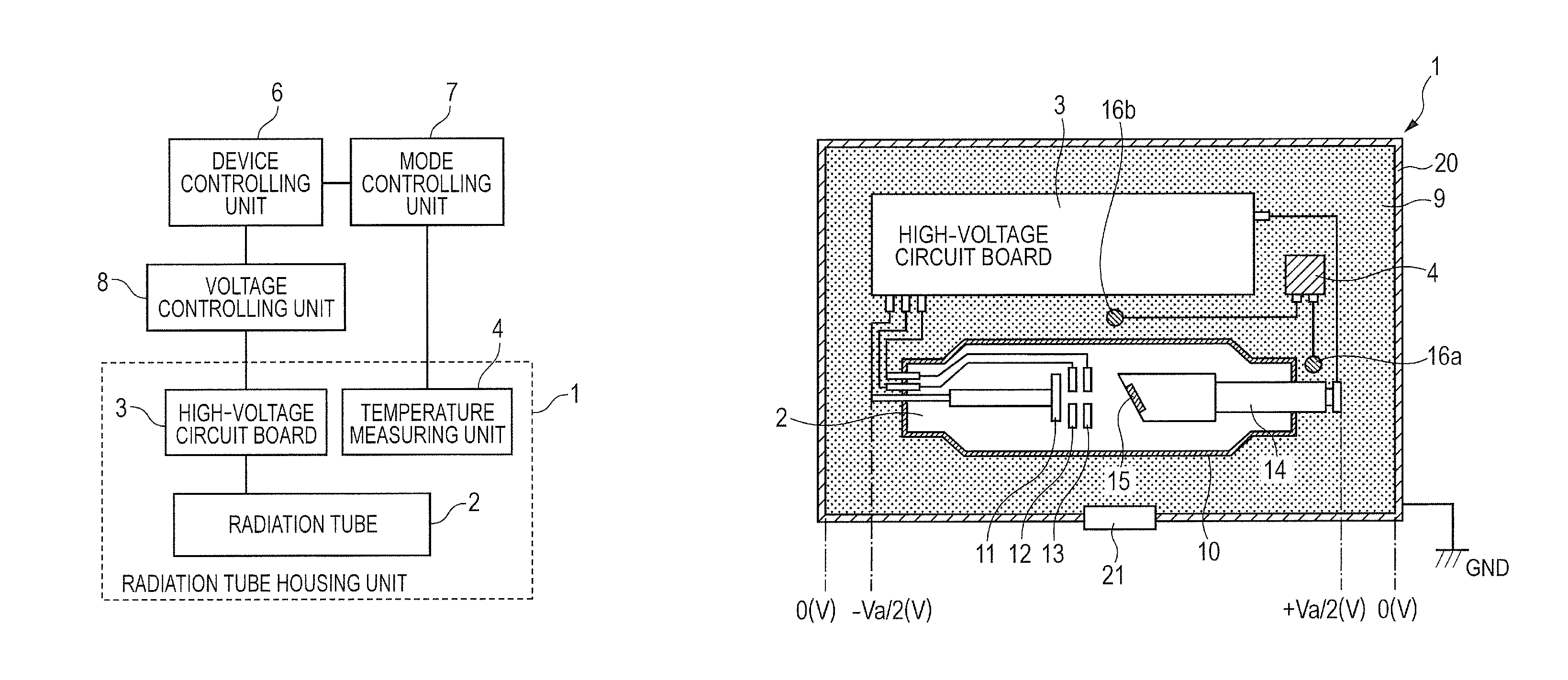
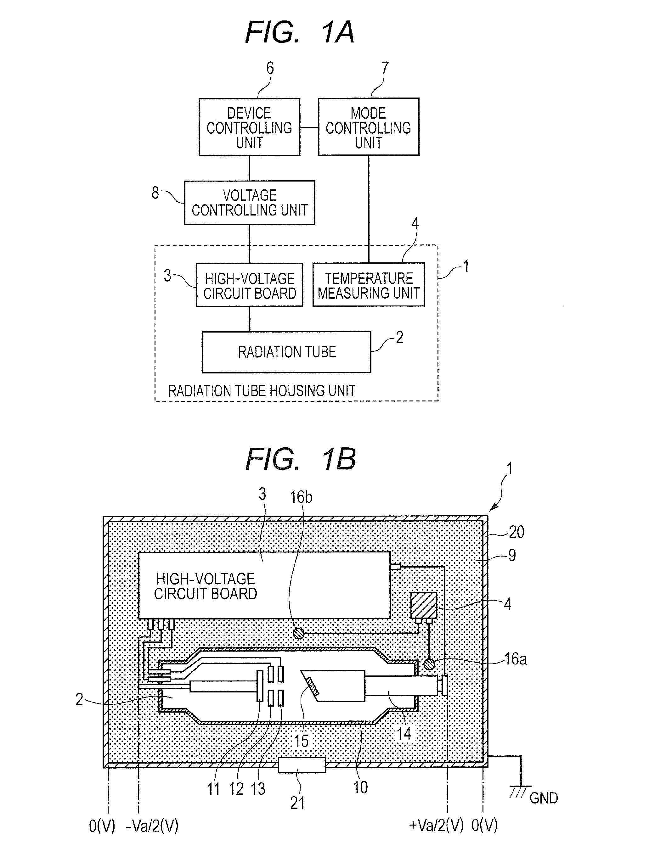
[0022]FIG. 1A is a constructional diagram of a radiation generating apparatus of the first embodiment. FIG. 1B is a schematic cross sectional view of a radiation tube housing unit 1 in FIG. 1A. In the radiation tube housing unit 1, a radiation tube 2 and a high-voltage circuit board 3 are enclosed in a housing container 20. The housing unit 1 has a radiation transmitting window 21 for extracting a radiation emitted from the radiation tube 2 to an outside. A remaining space in the housing container is filled with an insulating liquid 9.

[0023]The insulating liquid 9 has a role as a coolant of the radiation tube 2. It is desirable to use an electrical insulating oil as an insulating liquid 9. A mineral oil, a silicone oil, or the like is preferably used. As another insulating liquid 9, a fluorine electrical insulating liquid can be mentioned.

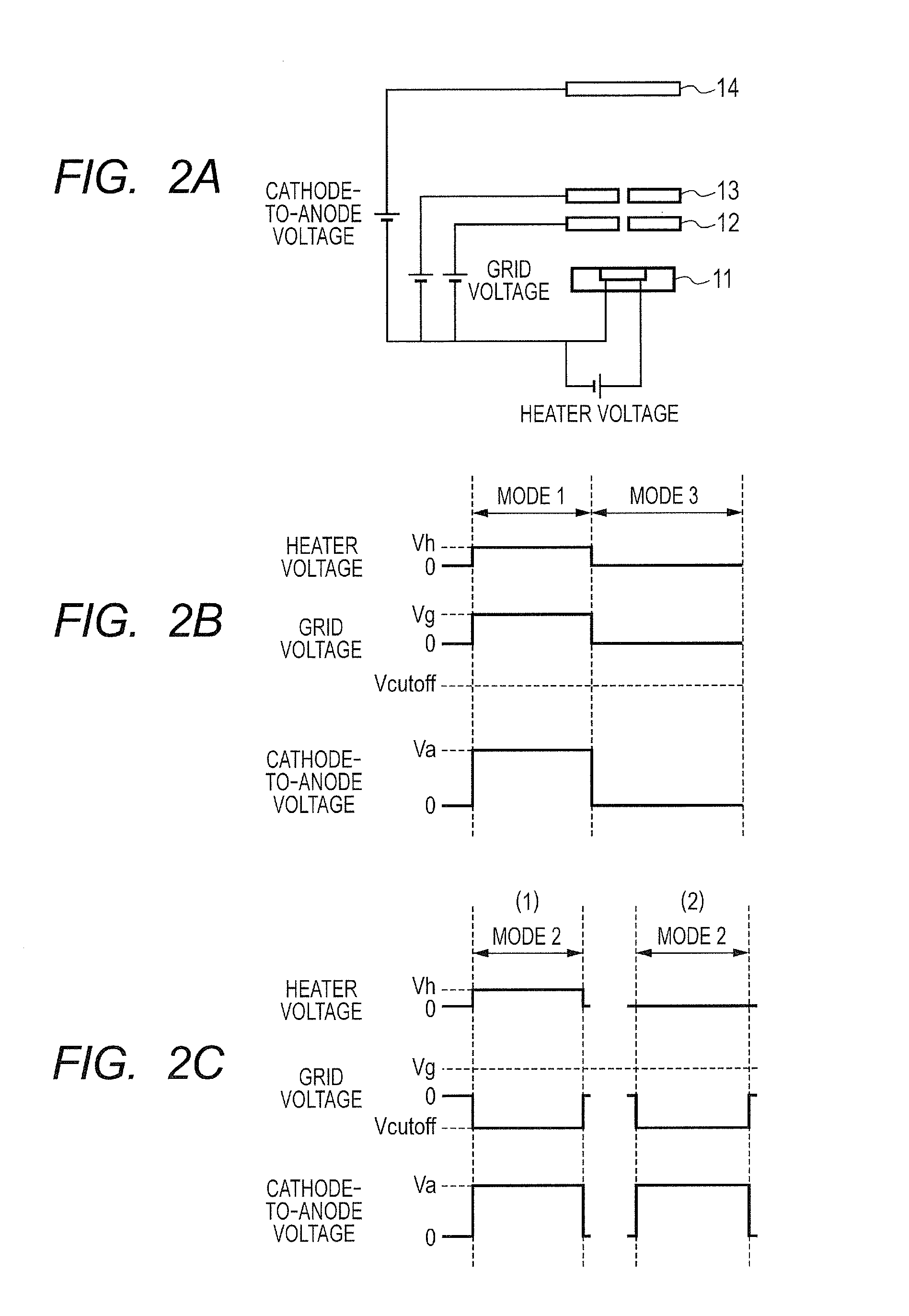
[0024]In the radiation tube 2, a cathode 11 and an anode 14 are provided in a vacuum container 10 made of glass or the like. An electron which is ...

second embodiment

[0038]Subsequently, another example of the radiation generating apparatus of the invention will be described by using FIG. 3. FIG. 3 is a schematic cross sectional view of the radiation tube housing unit 1 which can be applied to the radiation generating apparatus of the invention. In the embodiment, a transmitting type radiation tube is used in the radiation tube 2 and other portions can be constructed in a manner similar to those in the first embodiment. The embodiment is characterized by the driving in the stirring mode in a manner similar to the first embodiment. In FIG. 3, the same members as those in FIG. 1B are designated by the same reference numerals, 11 denotes the cathode, and 15 indicates the target. The target 15 is formed on the surface of a supporting board 17. A radiation emitted from the target 15 passes through the supporting board 17 and is emitted to she outside of the radiation tube 2. In the embodiment, the target 15 plays a role of the anode. A hot cathode suc...

third embodiment

[0040]Subsequently, a controlling method of the radiation generating apparatus of the invention will be described by using FIG. 4. The radiation generating apparatus of the first or second embodiment can be applied to the radiation generating apparatus. The embodiment relates to the controlling method which can be applied at the time of radiographing. FIG. 4 is a flowchart showing the controlling method.

[0041]First, when a photographing switch is pressed in a waiting state after a power source of the apparatus was turned on, a photographing mode (mode 1) is set and the photographing is started. The photographing is executed only for a preset time. After completion of the photographing, a temperature of a predetermined location in the housing container 20 is measured by the temperature measuring unit 4. If the temperature is lower than a predetermined temperature T1, the apparatus is returned to the waiting state. The waiting state is a state where although a power source circuit of ...


PUM

PropertyMeasurementUnit
voltageaaaaaaaaaa
voltagesaaaaaaaaaa
cut-off voltageaaaaaaaaaa

Abstract

In a radiation generating apparatus of the invention, a radiation tube having a cathode for emitting an electron and an anode for generating a radiation by an irradiation of the electron emitted from the cathode is enclosed in a housing container filled with an insulating liquid. The apparatus has a mechanism in which a voltage for allowing the insulating liquid to flow can be applied between the cathode and the anode in a state where the cathode does not emit any electron. Even when the generation of the radiation is stopped, the insulating liquid can be efficiently sufficiently cooled without providing mechanical stirring means, and a high reliability is obtained even for intermittent use.

Description

TECHNICAL FIELD[0001]The invention relates to a radiation generating apparatus which can be applied to a non-destructive X-ray photographing or the like in a medical equipment field and an industrial equipment field and relates to a radiographing system using the radiation generating apparatus.BACKGROUND ART[0002]Generally, in a radiation generating apparatus, by applying a high voltage between a cathode and an anode arranged in a radiation tube, an electron which is emitted from the cathode is irradiated to the anode, thereby generating a radiation such as an X-ray or the like. In the radiation generating apparatus like this, in order to assure withstanding voltage performance against the high voltage and to cool the radiation tube, such a structure that the radiation tube and a high-voltage circuit board are enclosed in a container filled with an insulating liquid is used. When the electron emitted from the cathode has entered the anode, since most of the incident energy is conver...

Claims


Application Information

Patent Timeline
Patent Type & Authority Patents(United States)
IPC IPC(8): H01J35/10H01J35/12G01N23/04H05G1/04H05G1/02
CPCH05G1/025H05G1/04G01N23/04H01J35/12H01J35/13
Inventor TAMURA, MIKIUEDA, KAZUYUKI
Owner CANON KK
Learn More