
Flow control valve

a technology of flow control valve and valve body, which is applied in the direction of valve operating means/release devices, pressure relieving devices on sealing faces, lighting and heating apparatus, etc., can solve the problems of short service life of sealing members, leakage of refrigerant, and the flow adjusting valv

Active Publication Date: 2016-03-15
ZHEJIANG SANHUA COMMERCIAL REFRIGERATION CONTROLS CO LTD
View PDF66 Cites 2 Cited by
  • Summary
  • Abstract
  • Description
  • Claims
  • Application Information

AI Technical Summary

Benefits of technology

The present application provides a flow adjusting valve that can balance pressures caused by the refrigerant on the valve rod and achieve different flow curves as required. The valve has an opening groove with a shape corresponding to the required flow curve, which is initially in communication with the valve port and has its circulation area gradually increased as the valve rod moves. The flow adjusting valve can achieve the required flow curve and ensure effective cooling.

Problems solved by technology

However, the flow adjusting valve has disadvantages as follows.
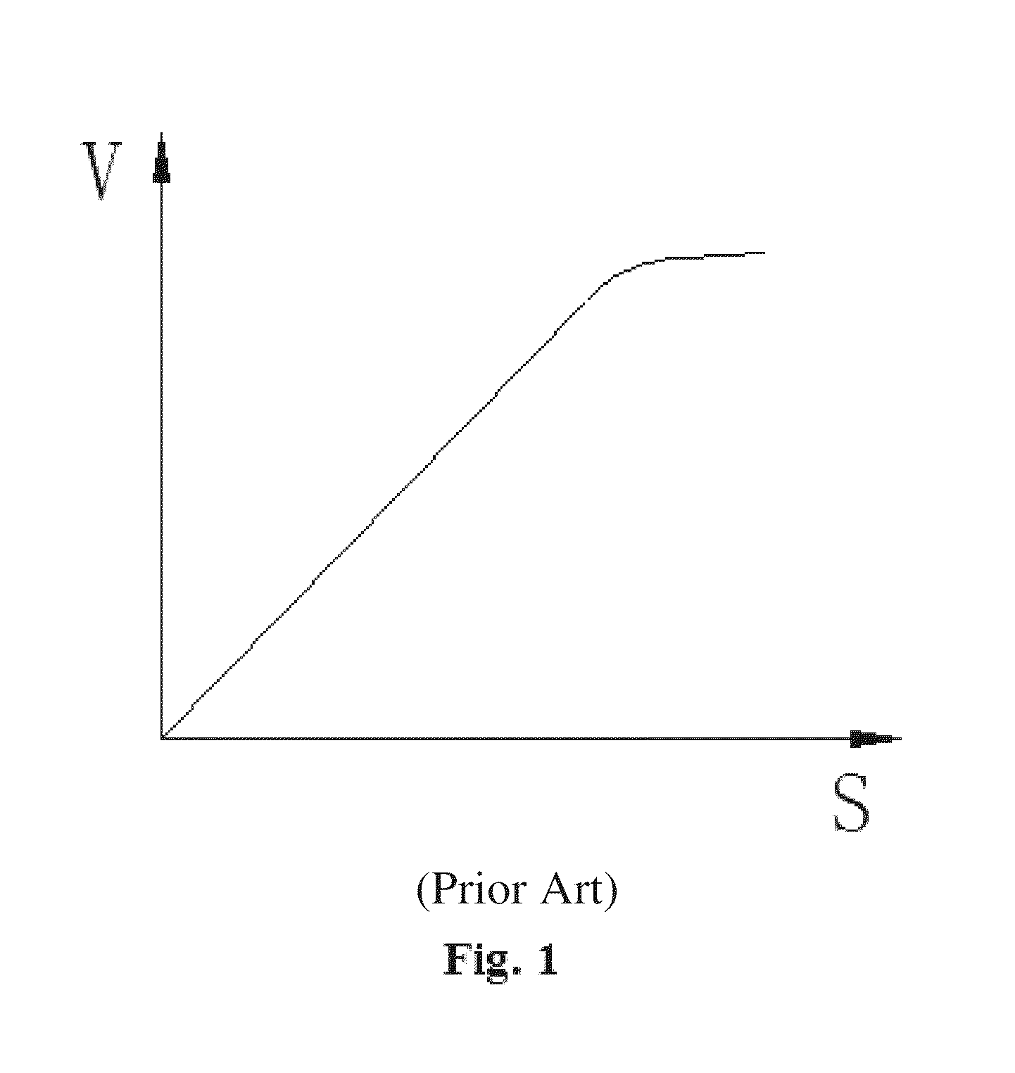
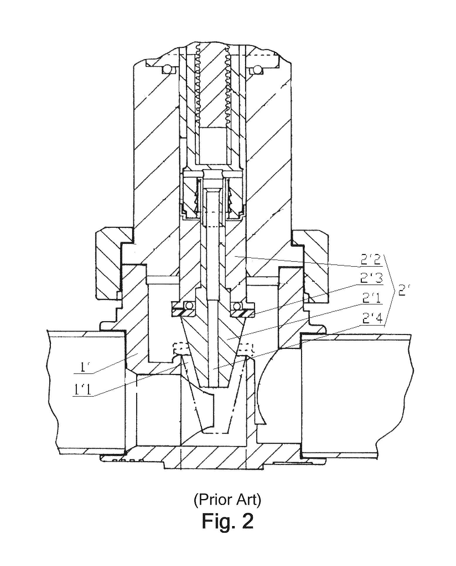
Since the impact force is large, after performing the opening and closing operations time and again, the sealing member 2′3 is easy to be deformed, resulting in the leakage of the refrigerant and a short service life of the sealing member.
The valve rod 2′ has a risk of being loosen and disconnected due to the bump and vibration in transportation or the vibration of the compressor in operation.

Method used


Image

  • Flow control valve
  • Flow control valve
  • Flow control valve

Examples


Embodiment Construction

[0059]A spirit of the present application is to provide a flow adjusting valve, with the structural design of the flow adjusting valve, pressures exerted by the refrigerant on the valve rod in the axial direction can be balanced while ensuring that the required flow curve can be obtained.

[0060]In order that those skilled in the art can better understand technical solutions of the present application, the present application is described in detail hereinafter in conjunction with the accompanying drawings and the embodiments.

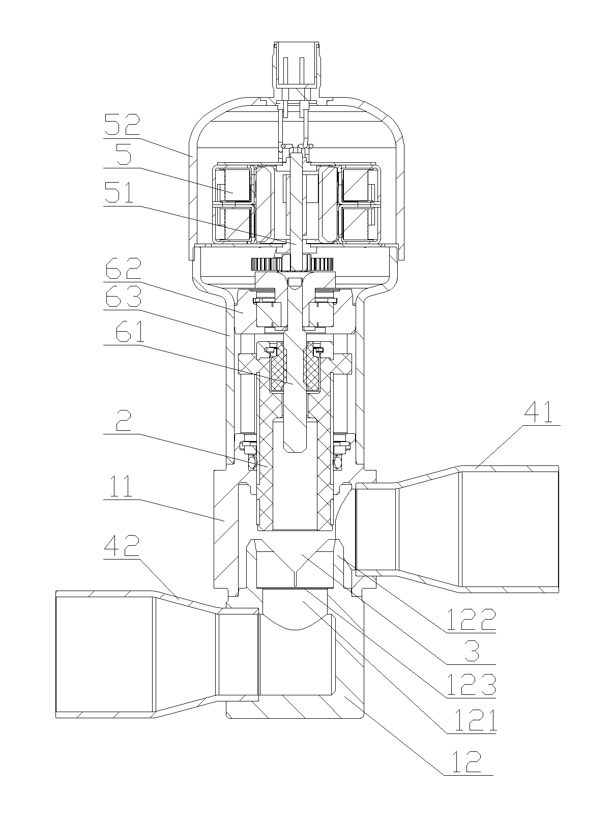
[0061]Referring to FIG. 4, FIG. 4 is a structural schematic view of a flow adjusting valve according to an embodiment of the present application.

[0062]The electronic expansion valve according to the present application is configured for adjusting the flow of the refrigerant. As shown in FIG. 4, the electronic expansion valve includes a motor shell 52 in which a motor 5 is provided. The output shaft 51 of the motor 5 is in transmission connection with the screw rod...


PUM


Abstract

A flow control valve comprises a valve seat (1) having a valve port (121) in its valve chamber and a valve rod (2) opening or closing the valve port (121). A sleeve protrusion part (122) projects upward from the valve port (121) in an axial direction thereof. The valve rod (2) is tubular and is cylindrical at the lower end. An open slot (3) matching with a flow curve is provided in the circumferential side wall of one of the sleeve protrusion part (122) and the lower end of the valve rod (2). One of the sleeve protrusion part (122) and the lower end of valve rod (2) is inserted into or extracted from the other to disconnect or connect the open slot (3) with the valve port (121). The structural design of the flow control valve can balance the refrigerant pressure on the valve rod (2) in the axial direction while ensuring that the required flow curve can be obtained.

Description

[0001]This application is the national phase of International Application No. PCT / CN2012 / 077519, titled “FLOW CONTROL VALVE” and filed on Jun. 26, 2012, which claims the benefit of priority to Chinese Patent Application No. 201110175952.3 entitled “FLOW ADJUSTING VALVE” and filed with the Chinese State Intellectual Property Office on Jun. 27, 2011, the entire disclosures of which are incorporated herein by reference.FIELD OF THE INVENTION[0002]The present application relates to the technical field of the fluid control component, and particularly to a flow adjusting valve.BACKGROUND OF THE INVENTION[0003]The flow adjusting valve is an important component of the refrigeration system, and is another one of four fundamental components of the refrigeration system besides the evaporator, the compressor and the condenser. Operation process of the flow adjusting valve is generally as follows: with the energizing or de-energizing of the coil device, the valve needle is driven to adjust the o...

Claims


Application Information

Patent Timeline
Patent Type & Authority Patents(United States)
IPC IPC(8): F16K47/08F16K5/06F16K31/50F16K3/24F25B41/06F16K5/10F16K3/34
CPCF16K5/0605F16K3/246F16K3/34F16K5/10F25B41/062F25B2341/0653Y02B30/72Y02B30/70F25B41/35F16K1/54F16K39/02F16K17/02F25B41/30
Inventor XU, GUOHUALV, MINGWANG, QINGYONG
Owner ZHEJIANG SANHUA COMMERCIAL REFRIGERATION CONTROLS CO LTD
Learn More