Form measuring instrument

a technology of measuring instruments and shapes, applied in the direction of instruments, electric/magnetic roughness/irregularity measurements, electric/magnetic measuring arrangements, etc., can solve the problems of stick slippage, non-smooth movement, etc., and achieve the effect of flexible installation and efficient installation spa

Active Publication Date: 2016-03-15
MITUTOYO CORP
View PDF18 Cites 15 Cited by
  • Summary
  • Abstract
  • Description
  • Claims
  • Application Information

AI Technical Summary

Benefits of technology

[0022]Examples of the vibration generator are a variety of actuators capable of vibration, i.e., a periodic mechanical movement, in response to an input signal. Among the above, an electrostrictive element such as a piezoelectric element is especially usable. Such an element, which is simple in structure and cost-friendly, contributes to providing a reliable measurement result.
[0040]With the above arrangement, the displacement detector may be installed along the side opposite to the tip of the stylus across the turn shaft of the stylus holder, thereby avoiding, for instance, mechanical interference with the stylus and the tip of the stylus and thus ensuring the installation flexibility. Especially, when the vibration generator is installed near the tip of the stylus relative to the turn shaft of the stylus holder, respective installation spaces can be efficiently ensured.

Problems solved by technology

For instance, during the scanning movement of the tip of the stylus on a workpiece surface, the tip of the stylus sometimes temporarily sticks to the workpiece surface due to friction therebetween and unsticks in the next moment, resulting in a non-smooth movement (i.e., stick-slip).
Further, when a workpiece surface has a step, a projection or the like, the tip of the stylus having been moved along the workpiece surface is likely to be caught by such a portion to be hindered from continuously moving along the workpiece surface thereafter.
However, a reduction in a measurement force to reduce a friction force between a tip of a stylus and a workpiece surface as described above is accompanied by a decrease in the rigidity of a contact portion, so that a high-speed measurement becomes difficult to perform and thus operating efficiency is lowered.
Additionally, a low-friction coating using a diamond-based material or the like generally costs a lot and thus increases the cost of a form measuring instrument.
When a method such as vibrating a tip of a stylus is employed, a form measuring instrument is inevitably subject to structural limitations.
In contrast, in a form measuring instrument having such an arrangement that a stylus having one end provided with a tip is supported by a rotary measurement arm or stylus holder and the rotation of the stylus holder is detected to measure a displacement of the tip of the stylus, for instance, when only the stylus is vibrated to undergo a bending deformation, a relationship between a displacement of the tip of the stylus and a rotation angle of the stylus holder cannot be maintained and thus the displacement of the tip of the stylus cannot be detected by a detector near the stylus holder.

Method used


Image

  • Form measuring instrument
  • Form measuring instrument
  • Form measuring instrument

Examples


first exemplary embodiment

[0050]FIGS. 1 to 4 show a first exemplary embodiment of the invention.

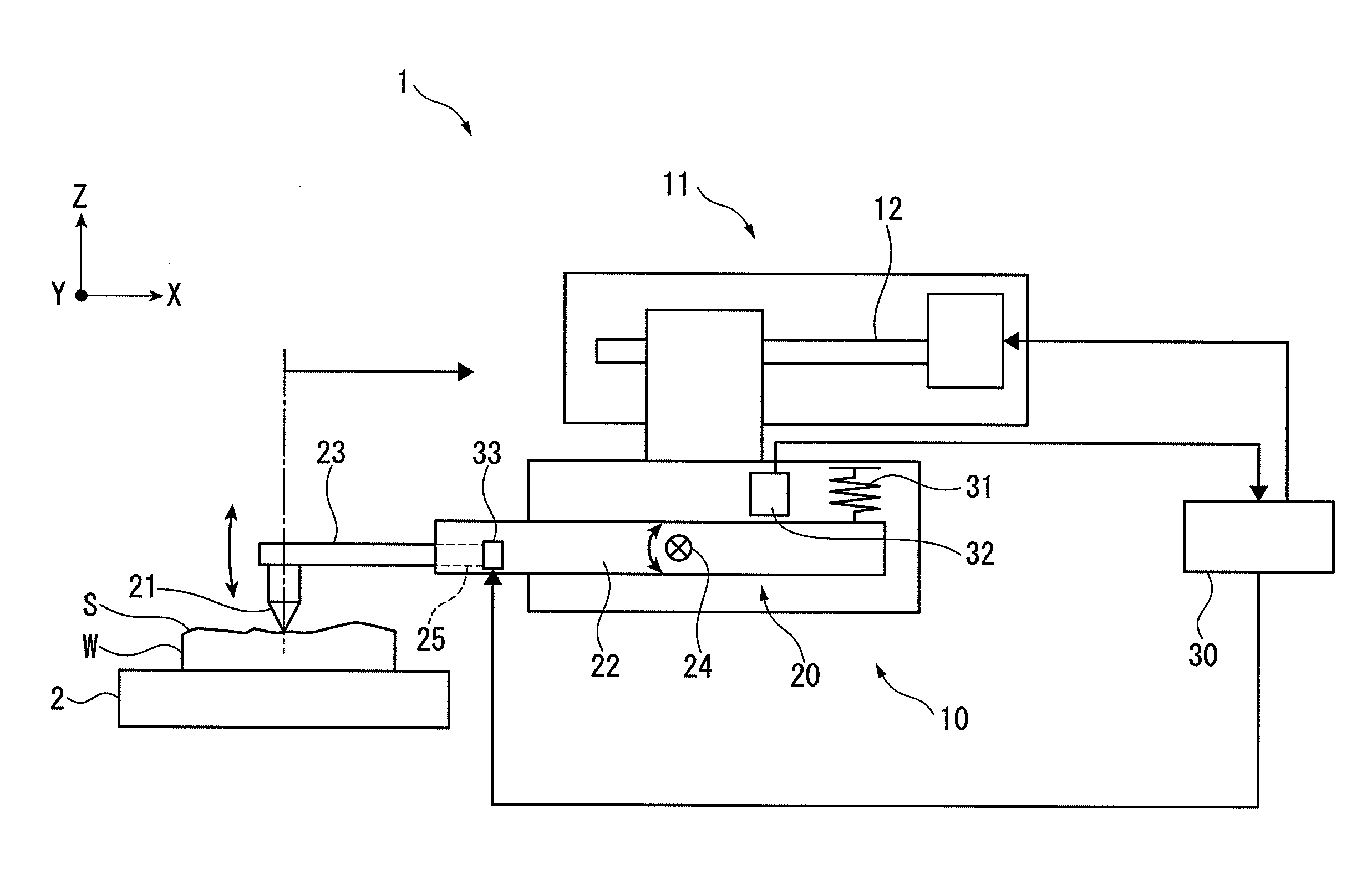
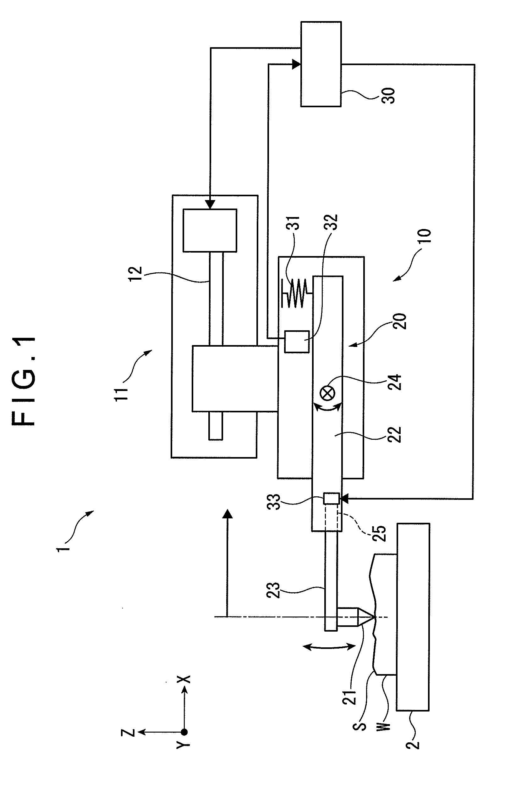
[0051]As shown in FIG. 1, a form measuring instrument 1 is adapted to measure a surface profile of a workpiece W mounted on a table 2.

[0052]Specifically, the form measuring instrument 1 includes: a body 10; a movable member 20 being rotatably supported by the body 10; and a tip of a stylus 21 being provided at an end of the movable member 20, the tip 21 being moved in a measurement direction (an X-axis direction in this exemplary embodiment) for a measurement operation while being in contact with a workpiece surface S. A Z-axial displacement of the tip of the stylus 21 is detected from a rotation condition of the movable member 20 during the measurement operation to measure a surface profile of the workpiece W (a contour in an X-Z plane).

[0053]The body 10 is supported by a support 11 and can be moved in the X-axis direction by a feed mechanism 12 provided in the support 11.

[0054]The support 11 may be supported by ...

second exemplary embodiment

[0089]FIG. 5 shows a second exemplary embodiment of the invention.

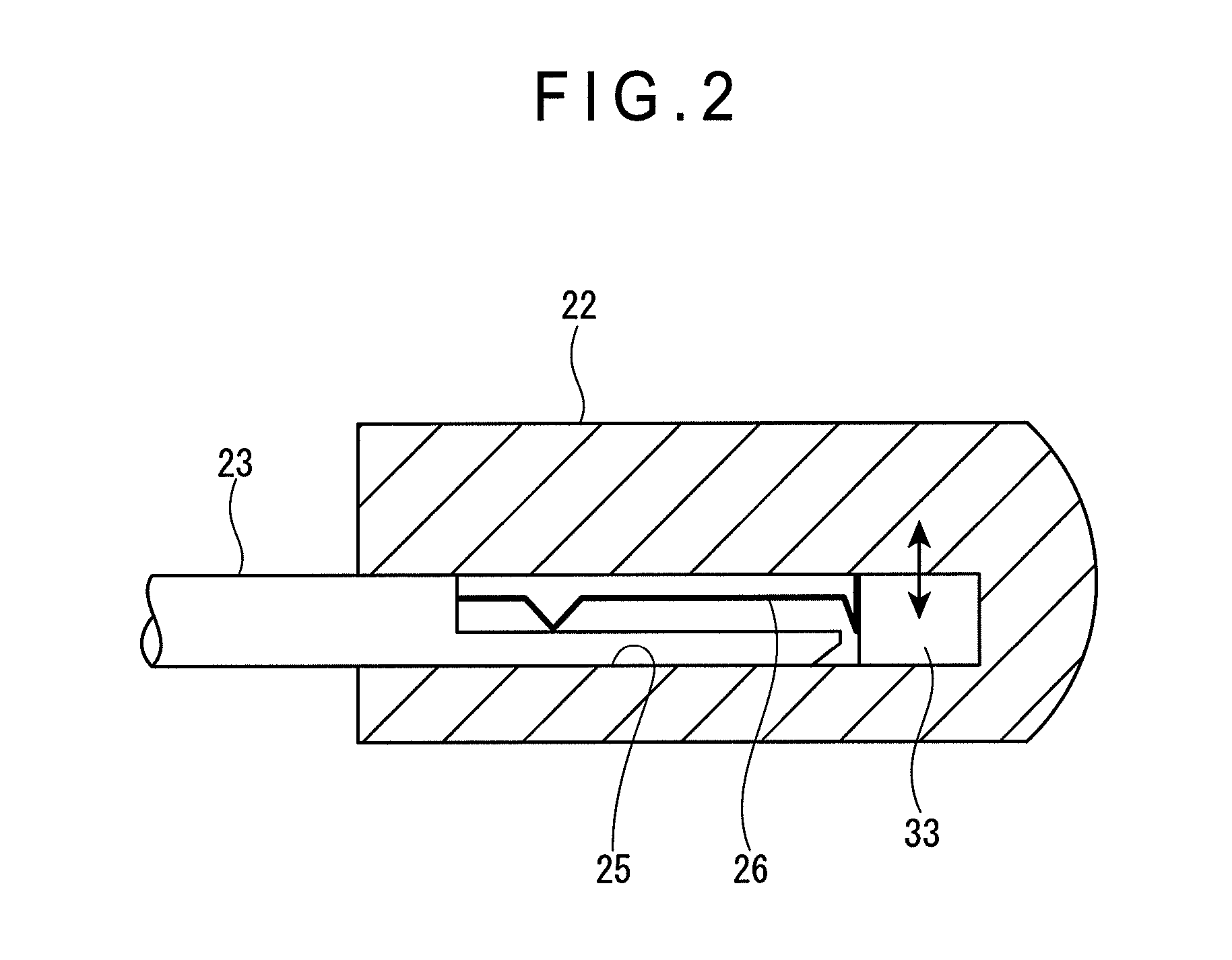
[0090]This exemplary embodiment has the same arrangement as the form measuring instrument 1 according to the first exemplary embodiment except that the vibration generator 33 is provided not in the connecting portion 25 but in the vicinity of the turn shaft 24.

[0091]This exemplary embodiment also offers the same effects as the first exemplary embodiment.

[0092]However, since the vibration generator 33 is not enclosed in the connecting portion 25, this exemplary embodiment requires an additional processing for, for instance, forming a hole or the like in the stylus holder 22 to enclose the vibration generator 33 therein.

[0093]Further, the vibration generator 33 is closer to the turn shaft 24 and remoter from the tip of the stylus 21, so that the second exemplary embodiment is inefficient and unfavorable in terms of vibration transmission to the tip of the stylus 21 as compared with the first exemplary embodiment.

[0094]I...

third exemplary embodiment

[0096]FIG. 6 shows a third exemplary embodiment of the invention.

[0097]This exemplary embodiment has the same arrangement as the form measuring instrument 1 according to the first exemplary embodiment except that the vibration generator 33 is provided not in the stylus holder 22 but in the stylus 23 at a portion supporting the tip of the stylus 21.

[0098]This exemplary embodiment also offers the same effects as the first exemplary embodiment.

[0099]However, since the vibration generator 33 is provided not in the stylus holder 22 but in the stylus 23, the vibration generator 33 is necessarily provided in each of possibly chosen styluses 23, which results in an increased installation cost. Further, replacement of the stylus 23 requires connection and disconnection of a signal line between the vibration generator 33 and the controller 30.

[0100]However, since the vibration generator 33 is provided in the stylus 23 at the portion supporting the tip of the stylus 21, the vibration from the ...


PUM


Abstract

A form measuring instrument includes: a body; a movable member including: a stylus holder being rotatably supported by the body; a stylus being held by the stylus holder; and a tip being provided at an end of the stylus and being contactable with a workpiece surface; a measurement-force-applying unit being adapted to generate a rotation force acting on the stylus holder to bring the tip of the stylus into contact with the workpiece surface; a displacement detector being provided to a portion of the stylus holder to detect a displacement of the stylus holder resulting from a rotation thereof; and a vibration generator being adapted to apply vibration to the stylus holder.

Description

[0001]The entire disclosure of Japanese Patent Applications No. 2013-039485 filed Feb. 28, 2013 is expressly incorporated by reference herein.TECHNICAL FIELD[0002]The present invention relates to a form measuring instrument used to measure a surface profile of a workpiece.BACKGROUND ART[0003]A form measuring instrument with a tip of a stylus that is brought into contact with a workpiece surface and moved therealong in a predetermined measurement direction has been used to measure the workpiece surface (see Patent Literature 1: JP-A-6-129810).[0004]In such a contact-type form measuring instrument, a contact condition of the tip of the stylus on a workpiece surface comes to affect a measurement result as the measurement accuracy improves.[0005]For instance, during the scanning movement of the tip of the stylus on a workpiece surface, the tip of the stylus sometimes temporarily sticks to the workpiece surface due to friction therebetween and unsticks in the next moment, resulting in a ...

Claims


Application Information

Patent Timeline
Patent Type & Authority Patents(United States)
IPC IPC(8): G01B5/20G01B5/28G01B3/00G01B7/28G01B7/34
CPCG01B5/20G01B3/008G01B5/28G01B7/28G01B7/34
Inventor MATSUMIYA, SADAYUKIHIDAKA, KAZUHIKO
Owner MITUTOYO CORP
Why Eureka
Try Eureka