Wireless radio access point configuration

a wireless radio and configuration technology, applied in the field of computer networks, can solve the problems of .4 ghz radio aps, underutilization of potential bandwidth, and high cost of wireless network architecture, and achieve the effect of reducing gain loss

Active Publication Date: 2016-03-15
FORTINET
View PDF5 Cites 139 Cited by
  • Summary
  • Abstract
  • Description
  • Claims
  • Application Information

AI Technical Summary

Benefits of technology

[0011]Methods and systems are described for configuring an access point (AP) so as to optimally use channels of AP radios, prevent co-channel interference and also address antenna coupling in order to reduce loss of gain. According to one embodiment, a dual radio access point (AP) includes: a first radio, a first directional antenna, a first transmit queue, a second radio, a second directional antenna, a second transmit queue, a recipient device location determination module, a direction identification module, an interference detection module and a transmission module. The first radio operates at 2.4 GigaHertz (GHz) or 5 GHz. The first directional antenna is coupled to the first radio. The first transmit queue has stored therein packets for transmission by the first radio. The second radio operates at 5 GHz. The second directional antenna is coupled to the second radio. The second transmit queue has stored therein packets for transmission by the second radio. The recipient device location determination module is configured to compute locations of recipient devices of the packets stored in the first transmit queue and the packets stored in second transmit queue. The direction identification module is configured to calculate angles within a horizontal plane to direct the first directional antenna and the second directional antenna based on the computed locations. The interference detection module is configured to determine whether interference would take place if the packets stored in the first transmit queue and the packets stored in the second transmit queue are transmitted based on the calculated angles and estimating timing of transmission. The transmission module is configured to transmit the packets stored in the first transmit queue and the packets stored in the second transmit queue via the first radio and the second radio, respectively, without interference between the first directional antenna and the second directional antenna by rescheduling one or more of the packets stored in the first transmit queue or one or more of the packets stored in the second transmit queue when the interference detection module determines that interference would otherwise take place between the first directional antenna and the second directional antenna.

Problems solved by technology

As such, high-density configurations of 2.4 GHz radio APs contributes to underutilization of potential bandwidth that may be provided by the 2.4 GHz radio APs.
In continuation, in existing solutions that have both 2.4 GHz and 5 GHz radios in a dual AP, in a building that requires a large number of APs to be configured, say twenty non-overlapping 5 GHz channels, 20 different APs, each having a 5 GHz radio would be needed, which further makes the wireless network architecture expensive and substantially more cumbersome.
Therefore, the RF energy in the RF signals, when strong enough, may to cause clients to defer transmissions due to “busy” clear channel assessments.
In addition to the energy emitted by AP transmissions, energy emitted by client transmissions also needs to be considered and taken into account, which the existing solutions fail to do.
Yet another disadvantage of this configuration 100 relates to antenna coupling, which is caused when two antennas (configured to radiate and / or receive radio signals) exist in the same frequency band and are close to each other so as to cause energy from one antenna to couple with that of the other and appear as the received signal.
Such received signals result in loss of gain and directional transmission overlap, which is undesirable.

Method used


Image

  • Wireless radio access point configuration
  • Wireless radio access point configuration
  • Wireless radio access point configuration

Examples


Embodiment Construction

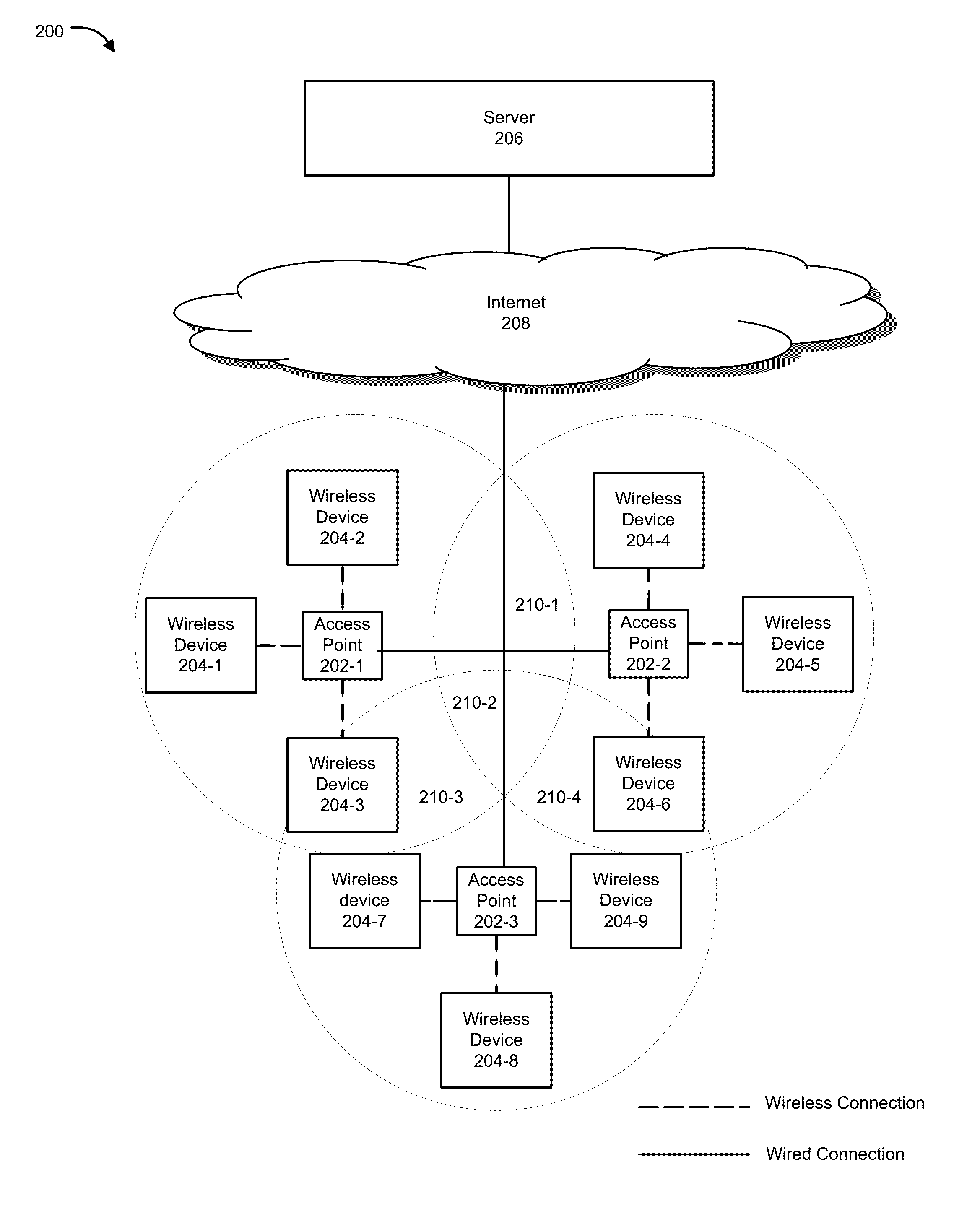
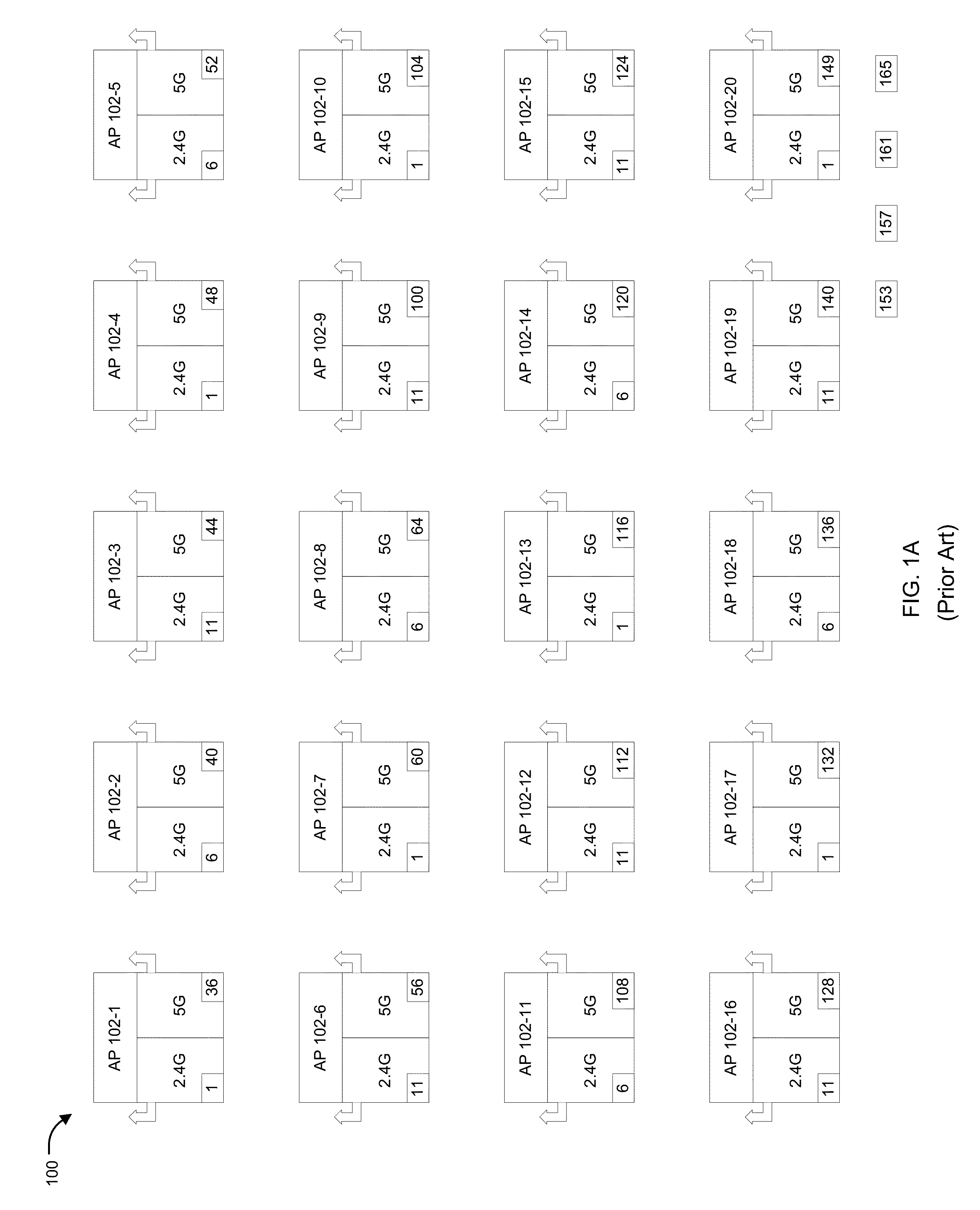
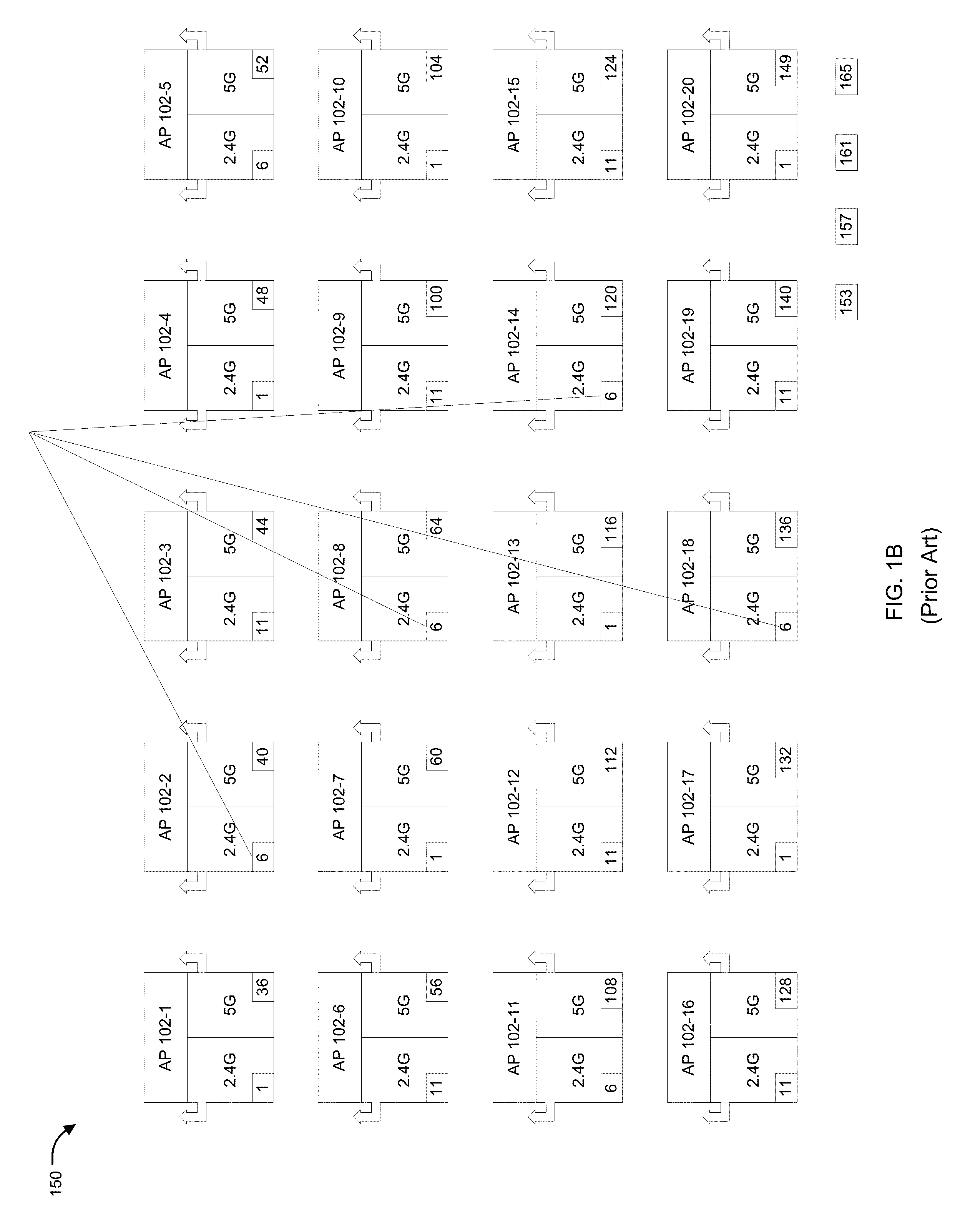
[0028]Methods and systems are described for configuring an access point (AP) so as to optimally use channels of AP radios, prevent co-channel interference and also address antenna coupling in order to reduce interference between two radios transmitting and receiving at the same time on same channel or adjacent channels. Embodiments of the present disclosure generally relate to methods and systems for implementing dual-radio access points in a wireless network configuration. Various embodiments of the present disclosure relate to methods and systems for configuring, arranging, placing or otherwise locating radio access points in a manner that allows optimum utilization of available radio channels, and have lower channel interference for a given coverage area. One aspect of the present disclosure provides a dual concurrent 5 GHz radio AP, wherein each 5 GHz radio of the AP is configured with a different channel in a manner such that overall throughput of the AP is maximized and co-cha...


PUM


Abstract

Methods and systems for configuring an access point (AP) are provided. According to one embodiment, a dual radio AP includes: two radios, a first operating at 2.4 GigaHertz (GHz) or 5 GHz and a second operating at 5 GHz; first and second directional antennas coupled to the first and second radios, respectively; first and second transmit queues buffering packets for transmission by the first and second radios, respectively; a location determination module configured to compute locations of recipient devices of the packets; a direction identification module configured to calculate angles to direct the directional antennas based on the computed locations; an interference detection module configured to determine whether interference would take place if the packets are transmitted based on the calculated angles and estimated timing of transmission; and a transmission module configured to transmit the packets without interference between the directional antennas by rescheduling packets if necessary.

Description

COPYRIGHT NOTICE[0001]Contained herein is material that is subject to copyright protection. The copyright owner has no objection to the facsimile reproduction of the patent disclosure by any person as it appears in the Patent and Trademark Office patent files or records, but otherwise reserves all rights to the copyright whatsoever. Copyright© 2014, Fortinet, Inc.BACKGROUND[0002]1. Field[0003]Embodiments of the present disclosure generally relate to the field of computer networks. In particular, various embodiments relate to methods and systems for configuring, arranging, placing or otherwise locating radio access points in a manner that allows optimum utilization of available radio channels and have lower channel interference for a given coverage area.[0004]2. Description of the Related Art[0005]Wireless communication systems are widely deployed to provide various communication services such as voice, video, packet data, messaging, broadcast, etc. With the number of wireless-enable...

Claims


Application Information

Patent Timeline
Patent Type & Authority Patents(United States)
IPC IPC(8): H04W88/10H04W24/02H04W84/12
CPCH04W88/10H04W24/02H04W84/12H04W72/54H04W72/541H04W72/0453
Inventor AKHAVAN-SARAF, KOROUSHREVERTE, JOSE LUIS VILLARREAL
Owner FORTINET
Why Eureka
Try Eureka