System and method for automated tool management

a tool management and system technology, applied in the field of system and method for automated tool management, can solve the problems of easy to distinguish one tool from another, time-consuming to perform investigative work, and insufficient critical information about the tool

Active Publication Date: 2016-03-22
DIFR TEK DIGITAL LLC
View PDF24 Cites 8 Cited by
  • Summary
  • Abstract
  • Description
  • Claims
  • Application Information

AI Technical Summary

Problems solved by technology

Often times these tools are sent from one plant to another, but critical information related to the tool is not provided, is incomplete, or is lost.
This can be very problematic in a manufacturing setting where multiple tools are used, as it is not necessarily easy to distinguish one tool from another by mere inspection.
It can be time consuming to perform the investigative work required to determine the identity of a specific tool, or even wasteful or dangerous if a misidentified tool is inadvertently used.

Method used


Image

  • System and method for automated tool management
  • System and method for automated tool management
  • System and method for automated tool management

Examples


Embodiment Construction

[0018]The following detailed description is of the best currently contemplated modes of carrying out exemplary embodiments of the disclosure. The description is not to be taken in a limiting sense, but is made merely for the purpose of illustrating the general principles of the disclosure, since the scope of the disclosure is best defined by the appended claims.

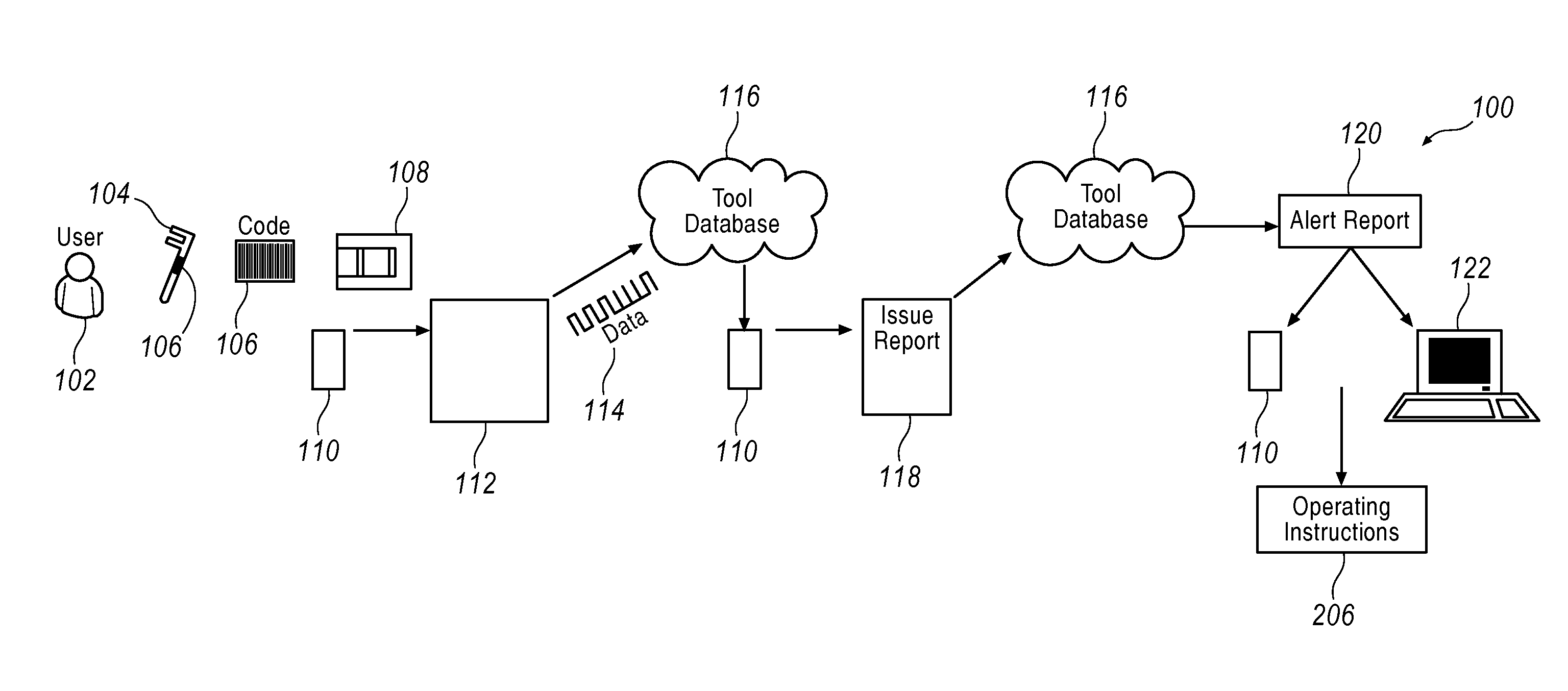
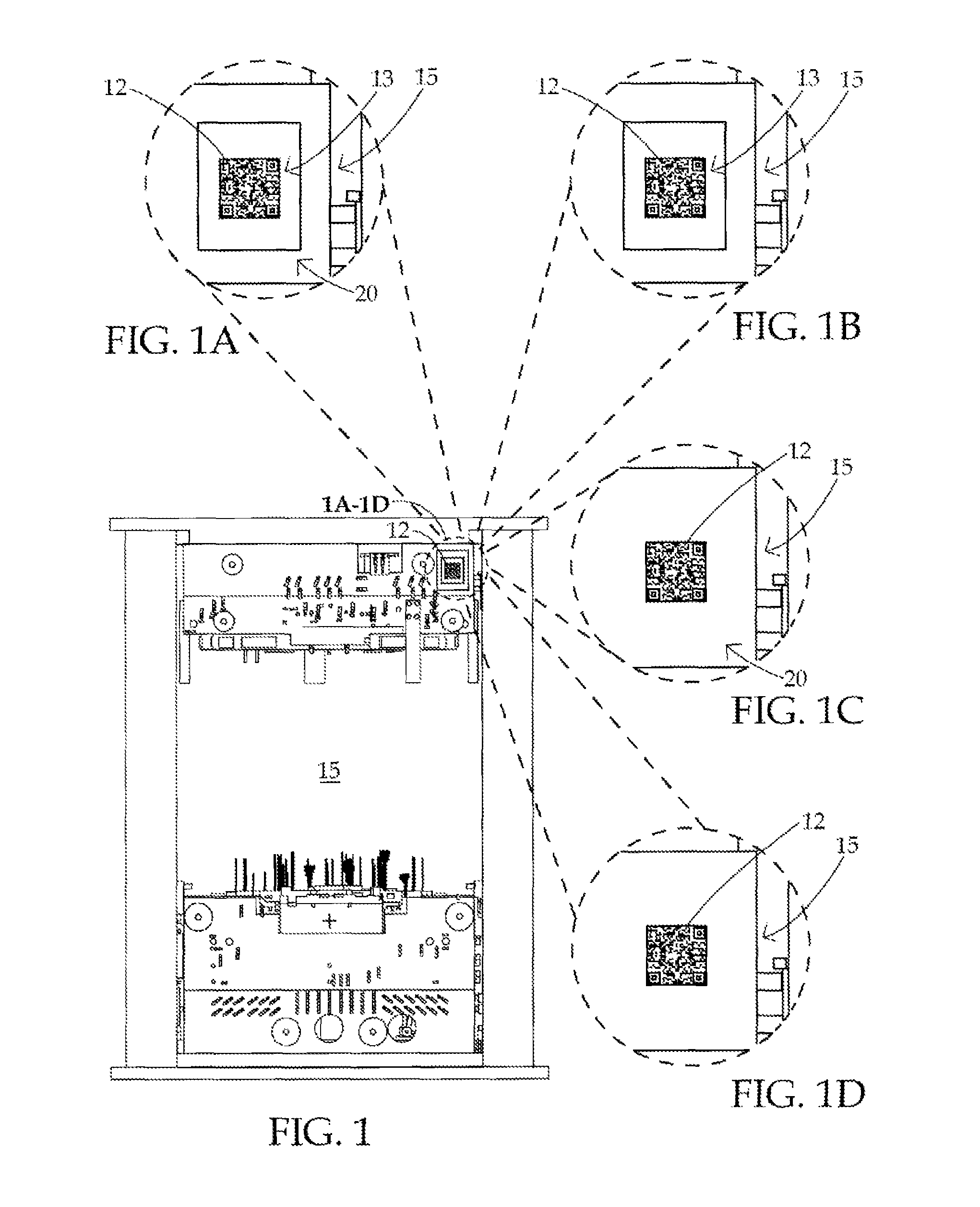
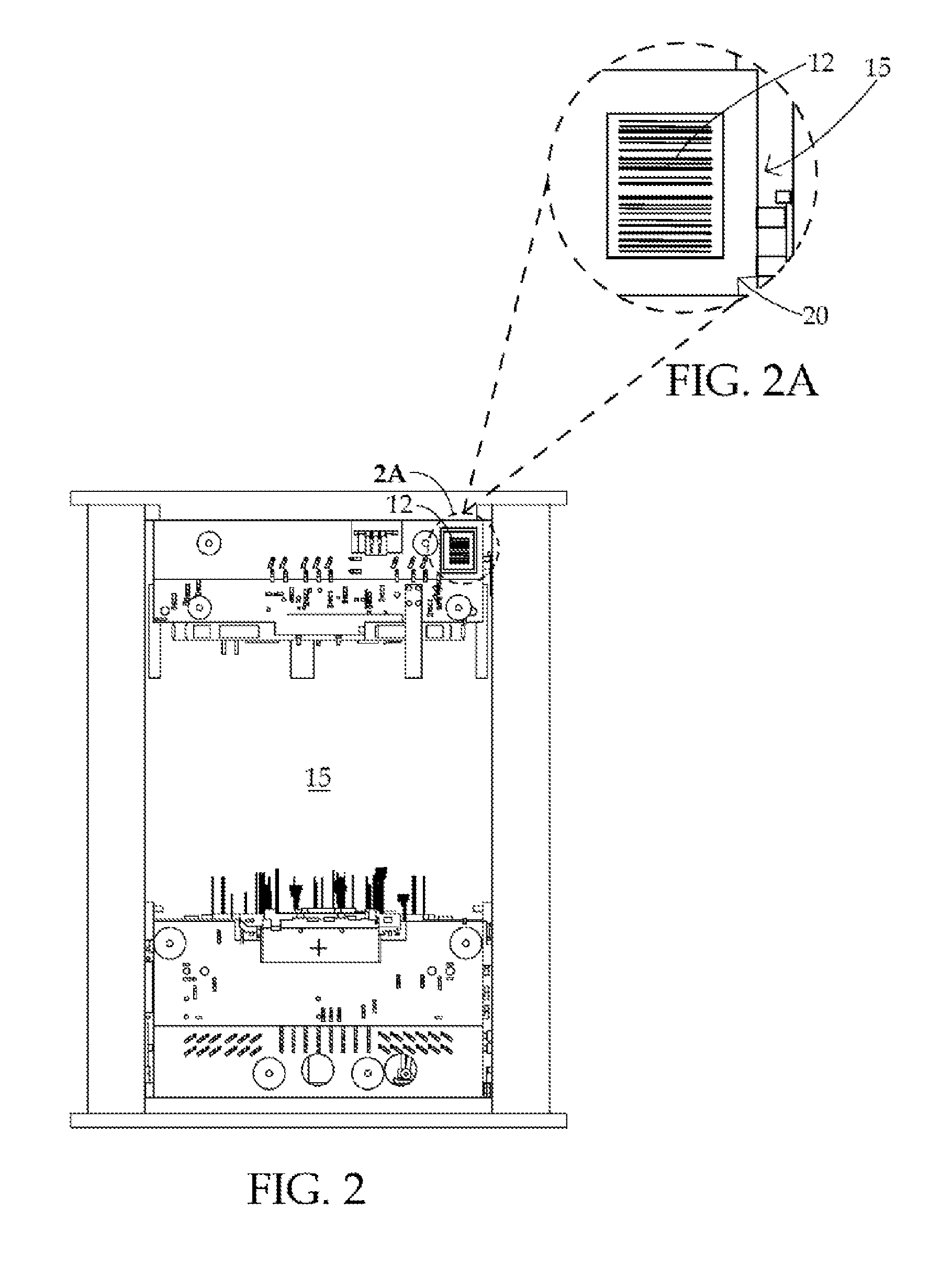
[0019]Referring to FIG. 1, an information management system 10 may include, but is not limited to, a barcode 12, a barcode plate 13, a tool 15, a plaque 20, a barcode reader 25, a processor 30, and an output display 35. As used herein, a “tool” is a device, machine or apparatus that is portable and used in the manufacture of goods and products. Examples of “tools” include tool and dies, molds, controllers, machines, fixtures, hot runner systems, and secondary equipment.

[0020]As shown in FIG. 1A, barcode 12 maybe situated on barcode plate 13. which is affixed to plaque 20, with plaque 20 attached to a tool 15. In this manner b...


PUM

PropertyMeasurementUnit
dimensionsaaaaaaaaaa
surface dimensionsaaaaaaaaaa
adhesionaaaaaaaaaa

Abstract

A system of using machine readable labels affixed to tools for managing information related to those tools. The barcode is affixed to a tool so that the barcode does not interfere with the tool. By scanning the barcode on the specific tool, a user is able to access pertinent information related to that tool. Examples include specifications, recalls, hours of usage, liens, etc. Also, a method of reporting metrics of the history of a tool that includes the ability to create, report, store, and communicate machine tool details, parameters, usage, issues, maintenance actions, and or problems. Also, a method of generating a Preventative Maintenance alert report. Additionally, a method of tracking the lifecycle count of a tool. Also, a method of auto-populating a tool database. Finally, a method of tracking tool locations and updating tool metrics utilizing a GPS- and camera-enabled cell phone.

Description

RELATED APPLICATIONS[0001]This application is a Continuation-In-Part Application of U.S. application Ser. No. 13 / 690,097, filed Nov. 30, 2013, which claims the benefit of U.S. Application No. 61 / 605,366, filed Mar. 1, 2012, the contents of which are incorporated herein in their entirety.FIELD OF TECHNOLOGY[0002]The present disclosure relates to systems using machine readable labels on tools. More specifically it is a system of using machine readable labels, such as barcodes, that are integrated with, or affixed to, molds and dies, or other assets used in the manufacturing of product, thereby permitting a user to access critical information, report issues, set alerts, and track tooling activity related to that specific tool.BACKGROUND[0003]Tools such as molds and dies are used to manufacture products such as plastic parts formed by injection molding. In order to use a given tool properly, the operator must possess certain information about the tool. Such critical information might in...

Claims


Application Information

Patent Timeline
Patent Type & Authority Patents(United States)
IPC IPC(8): G06F17/00G06Q10/06G05B19/4093G05B19/4065G06K19/06B29C45/17B29C31/00G05B19/418
CPCG05B19/4065G05B19/40938G06K19/06028G06Q10/06B29C31/006B29C2045/1796G05B19/4183G06Q10/087
Inventor O'BRIEN, PATRICIA L.O'BRIEN, GEOFFREY C.BROLLEY, SEAN M.DRACA, PREDRAG
Owner DIFR TEK DIGITAL LLC
Why Eureka
Try Eureka