Connector assembly

a technology of connecting parts and connectors, applied in the direction of couplings/cases, coupling device connections, securing/insulating coupling contact members, etc., can solve the problems of deterioration of sealing performance, part of the sealing member is lifted from the groove part of the housing, excessive expansion, etc., to achieve smooth and reliable engagement of the convex par

Active Publication Date: 2016-03-22
YAZAKI CORP
View PDF11 Cites 9 Cited by
  • Summary
  • Abstract
  • Description
  • Claims
  • Application Information

AI Technical Summary

Benefits of technology

[0011]According to the connector assembly having the structure as described above in the configuration (1), in case where a force in the circumferential direction is exerted on the sealing member, this force can be reliably loaded by engagement between the convex part and the concave part. Therefore, for example, even in such a case that a worker happens to touch the sealing member at a time of fitting the connector assembly to the mounting hole of the mating device to be connected, and the force in the circumferential direction is exerted on the sealing member, it is possible to effectively prevent rotation of the sealing member in the circumferential direction with respect to the housing.
[0013]According to the connector assembly having the structure as described above in the configuration (2), it is possible to smoothly and reliably engage the convex part and the concave part with each other, and it is also possible to keep them in an engaged state.

Problems solved by technology

Therefore, when the sealing member is displaced with respect to the housing in a circumferential direction, there is an anxiety of such trouble that a part of the sealing member is lifted from the groove part of the housing or excessively expanded.
In case where the sealing member is attached in this state, when the housing is fitted to the mounting hole, tight contact of the sealing member with respect to the groove part of the housing and the inner peripheral part of the mounting hole is not uniformly performed in the circumferential direction, and hence, deterioration of sealing performance is incurred.

Method used


Image

  • Connector assembly
  • Connector assembly
  • Connector assembly

Examples


Embodiment Construction

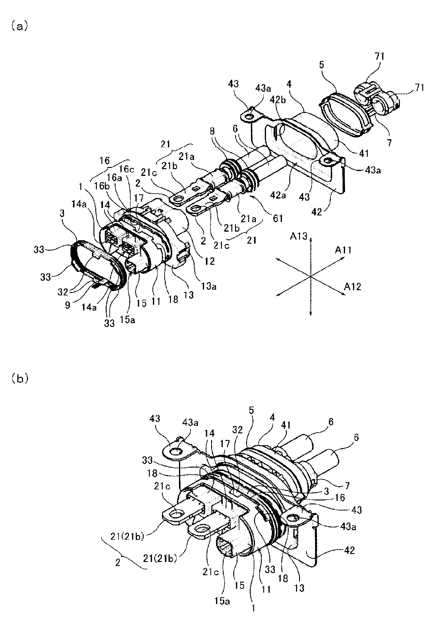
[0016]A connector assembly according to the present invention will be described below, referring to the attached drawings. The connector assembly according to the present invention is an interface member for electrically interconnecting (specifically, electrically connecting and disconnecting) a wire-side terminal provided on an end portion of an electric wire and a device-side terminal provided on a mating device to be connected. Uses of the connector assembly are not particularly limited. For example, it is possible to suppose, as an appropriate example, such a case that an inverter of an electric motor which is mounted on a vehicle such as an electric car driven using the electric motor, a hybrid car driven using both an engine and the electric motor is connected to an electric junction box (a junction box) of a power supply device for supplying an electric power to the electric motor.

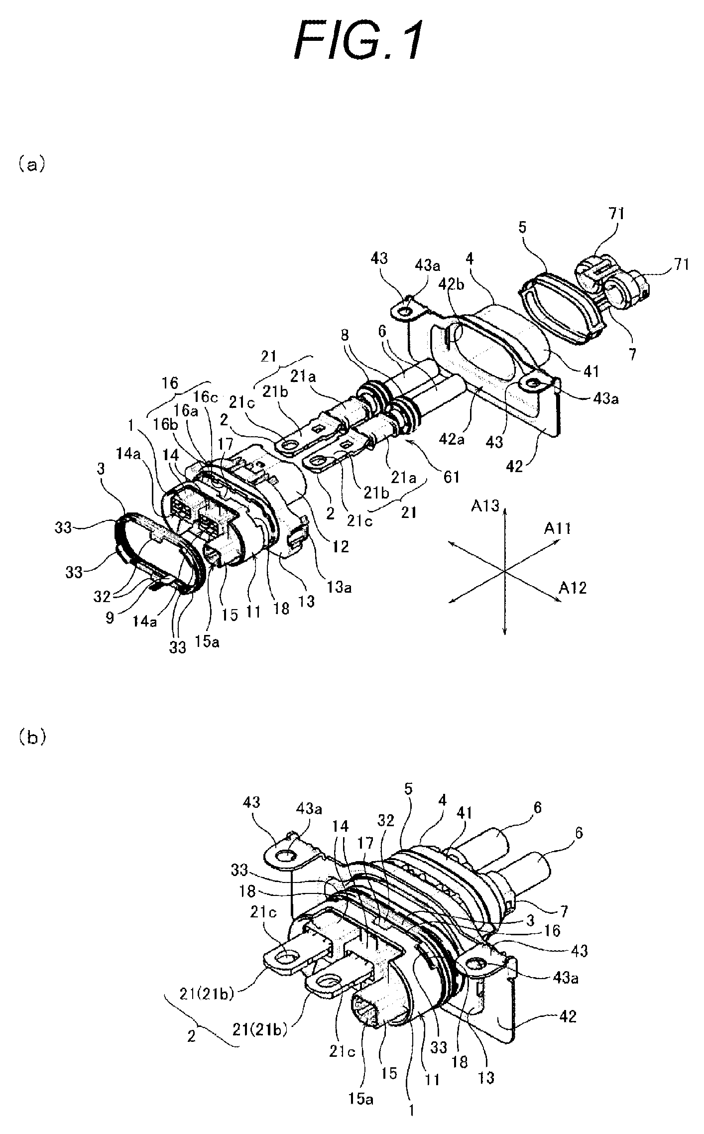
[0017]FIGS. 1(a) and 1(b) are diagrams showing an entire structure of a connector assembly accor...


PUM


Abstract

A connector assembly includes a housing (1) in which a wire-side terminal (2) is held, and which is fitted to a mounting hole formed in a casing 5 of a mating device to be connected, and a sealing member (3) which is attached to a groove part (16) formed in an outer peripheral part (11) of the housing thereby to keep an interior of the casing liquid tight. The sealing member (3) includes a convex part (33) formed in a curved part thereof, by protruding in a width direction from its peripheral edge part in a shape of an 10 annularly continued band. The groove part (16) includes a concave part (18) formed by denting a groove wall (16b), corresponding to the convex part (33). The convex part (33) and the concave part (18) are engaged with each other.

Description

TECHNICAL FIELD[0001]The present invention relates to a connector assembly for interconnecting terminals.BACKGROUND ART[0002]A vehicle such as an electric car which runs using an electric motor, and a hybrid car which runs using both an engine and an electric motor, is driven by an electric power which is supplied to the electric motor from a power supply mounted on the vehicle. In the hybrid car, for example, the electric motor and an inverter are connected to each other by an electric wire such as a motor cable. Moreover, the inverter is connected to an electric junction box (a junction box) which is provided in the power supply, and thus, the electric power is supplied from the power supply to the electric motor. On this occasion, the inverter and the electric junction box are connected to each other by way of a given connector member (a connector assembly).[0003]As an example of the connector assembly as described above, there has been known the connector assembly having such a ...

Claims


Application Information

Patent Timeline
Patent Type & Authority Patents(United States)
IPC IPC(8): H01R13/42H01R13/52
CPCH01R13/5202H01R2201/26
Inventor SHIGETA, YOSHINORINAKAYAMA, KOICHI
Owner YAZAKI CORP
Why Eureka
Try Eureka