Haptic feedback flow indicator

a flow indicator and haptic technology, applied in the direction of speed/acceleration/shock measurement, measurement devices, instruments, etc., can solve the problems of insufficient extinguishing agent, insufficient visibility beyond, and hazardous conditions within the burning structure, and achieve the effect of augmenting the haptic sensation

Active Publication Date: 2016-03-29
TASK FORCE TIPS
View PDF9 Cites 1 Cited by
  • Summary
  • Abstract
  • Description
  • Claims
  • Application Information

AI Technical Summary

Benefits of technology

[0016]The ideal indicator is small and lightweight, and is located in a position where its presence does not interfere with the normal hose handling techniques and habits of a firefighter. It should be positioned where the haptic feedback can be most readily felt. For a handheld device this is the hand since the hand grips the fire hose nozzle tightly and contains many nerves. In this way, the flow indicator can provide the fireman with haptic feedback of water flow.
[0021]All devices are subject to failure, and indicators are no exception. Ideally, a firefighter can remain safe under such a failure. If the indicator does not rotate until the flow reaches a certain minimum set point flow, then a firefighter may avoid entry into the conflagration if the indicator fails. This is safer than an indicator that provides the feedback before the set point is reached.

Problems solved by technology

Unfortunately, conditions within a burning structure are often times hazardous and include adversities such as a complete lack of visibility beyond the firefighter's mask as a result of the smoke and other airborne contaminates produced by the blaze.
Any less flow and there is insufficient extinguishing agent to overcome the heat of combustion, while any larger flow will extinguish the blaze.
Efforts to extinguish a blaze with less than the critical flow rate are a futile waste of time and a needless risk to firefighters.
However, there are a number of conditions that can cause the actual flow to differ from the desired flow.
The firefighter's safety and chance of success is compromised if the difference reduces the flow significantly.
This type of subjective judgment is not consistent or accurate, and does not insure that conditions will remain constant once the attack has commenced.
During a fire, it would be difficult or impossible for a firefighter to see these devices not only because of the limited visibility but also because these devices would be located at the entrance of the nozzle, which is in a position near the elbow of the arm holding onto the nozzle and out of the normal field of view when one is trying to see the glow emitted from the blaze itself.
While it is certainly possible to transmit visual signals by wire, or wirelessly from a fire hose flow sensing device to a firefighter's eyes, these solutions require sophisticated electronics and result in several modes of failure.
For example, a heads-up display may have its battery run low, heat or shock may damage the electronics.
These indicators suffered the further drawback of the indicator spinning whenever there was flow through the nozzle, and thus providing little or no assistance in determining whether the flow is not merely present but also adequate.
Attempts at providing auditory feedback have not met with success because of the inconsistent noise level from fire to fire, and because auditory feedback diminishes the firefighter's critical ability to hear other sounds on the fire scene, including communications or other sounds on the fire scene that may signal dangerous conditions.
Furthermore, nozzle-mounted flow meters and flow indicators can add significantly to the length and weight of a fire hose nozzle, thereby diminishing the firefighter's effectiveness.
For these reasons, firefighters generally use flow meters and flow indicators only as training aids, and avoid them for operational use within the fire because the devices are regarded ineffective and detrimental to extinguishing the blaze.
Of the remaining human senses, it is probably not practical to use smell or taste to define when the proper flow is reached.
However, inasmuch as a given mass of water can be accelerated to virtually any velocity, it is not possible with present day nozzles to equate with certainty a sensed force with a specific flow.
Detecting a specific force is also a function of memory and experience, which are not always available, consistent, or reliable.
However, none of these vibrating devices have been employed to provide haptic feedback to a firefighter to indicate that a desired magnitude of water flow is being delivered.

Method used


Image

  • Haptic feedback flow indicator
  • Haptic feedback flow indicator
  • Haptic feedback flow indicator

Examples


Embodiment Construction

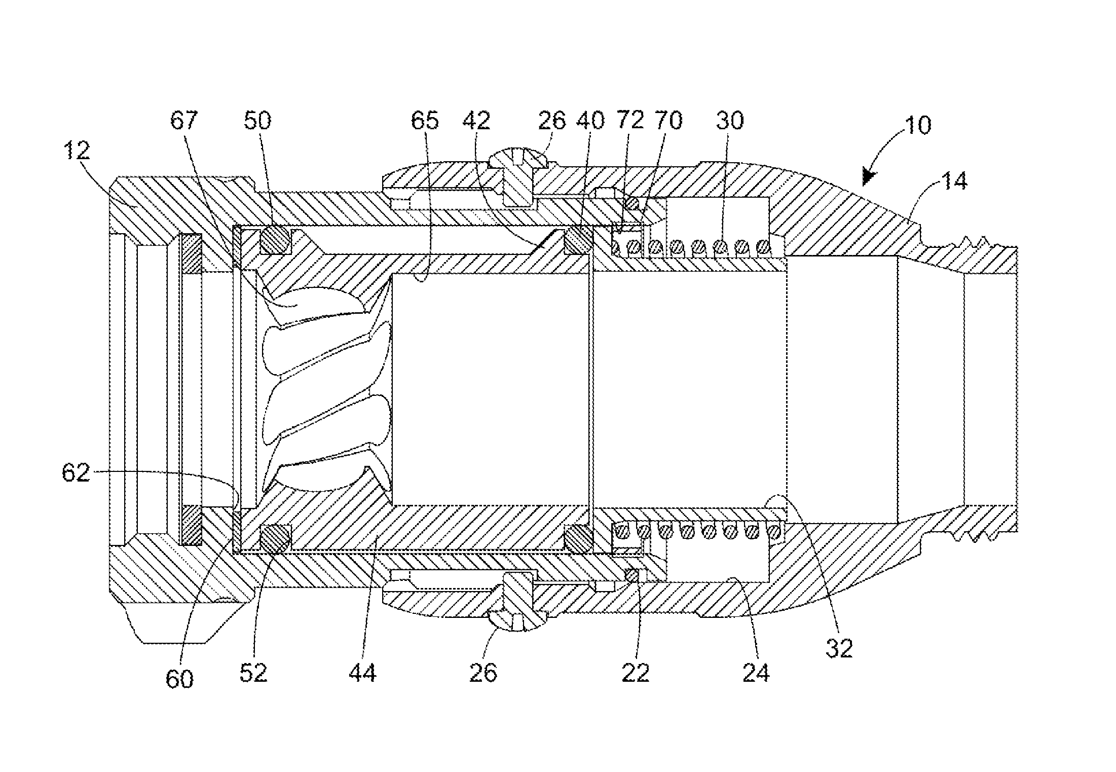
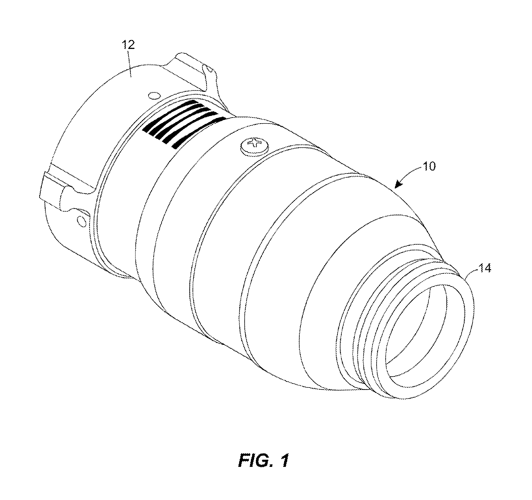
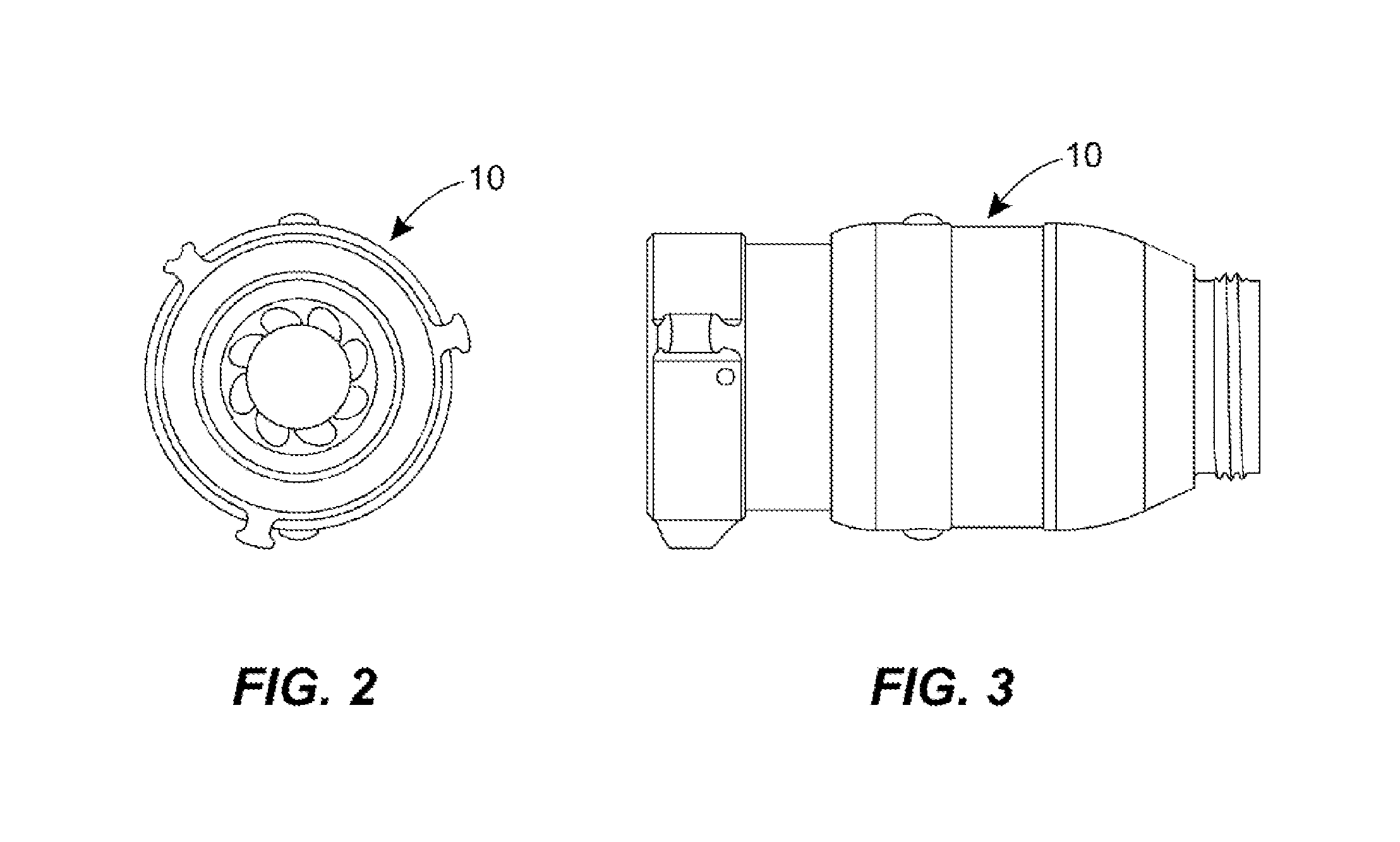
[0035]The most preferential haptic flow indicator 10 is depicted in FIGS. 1-8. A fire extinguishing agent such as water or a foam solution enters the indicator on the left hand side of the page by way of an inlet 12 through a fire fighting hose connection. The most prevalent type of connection used in the in USA for handheld nozzles is a female 1.5″ National Hose thread according to National Fire Protection Association standard NFPA 1963, but other thread sizes, types, genders may also be used. The indicator may have the fire hose connection integrally formed into the inlet of the indicator, or alternatively the inlet may include a fire hose coupling affixed to the distal end in a non-rotating manner, or so that it can rotate with respect to the inlet by use of a sliding fit or by bearing balls. A sealing connection to the fire hose discharge is made by use of a fire hose gasket of the like.

[0036]Water travels through the indicator and is discharged to the right through the outlet 1...


PUM


Abstract

A new haptic flow indicator has a spinner that is mounted for rotation and provides a discernable haptic feedback to a firefighter when liquid flow through the indicator falls in a selected range.

Description

[0001]This device is for use in conjunction with a fire hose nozzle. Its purpose is to give haptic feedback to the firefighter only when the flow to the nozzle exceeds a minimum threshold value.BACKGROUND[0002]Firefighters attempt to extinguish burning materials using extinguishing agents such as water, water with foam, or dry chemicals under a variety of circumstances. When battling structural fires in homes, commercial buildings, apartments, garages and the like it has been found that an interior attach is the most effective because the fireman can bring the extinguishing agent to the fire and apply it directly at the fuel source, thereby extinguishing the fire using a handheld nozzle. Unfortunately, conditions within a burning structure are often times hazardous and include adversities such as a complete lack of visibility beyond the firefighter's mask as a result of the smoke and other airborne contaminates produced by the blaze. Therefore, firemen rely heavily on their sense of...

Claims


Application Information

Patent Timeline
Patent Type & Authority Patents(United States)
IPC IPC(8): A62C37/50G01F1/05A62C37/08G01P13/00
CPCA62C37/50A62C37/08G01F1/053G01P13/004A62C31/03A62C31/28
Inventor MCMILLAN, STEWARTKOLACZ, DAVID, J.
Owner TASK FORCE TIPS
Why Eureka
Try Eureka