Rifle scope with adjusting aid

a technology of adjusting aid and rifle scope, which is applied in the direction of sighting devices, weapon components, weapons, etc., can solve the problems of limited vision field, troublesome parallax-related deviation of target image plane from sighting plane, and limited vision field

Active Publication Date: 2019-06-25
SCHMIDT & BENDER
View PDF26 Cites 2 Cited by
  • Summary
  • Abstract
  • Description
  • Claims
  • Application Information

AI Technical Summary

Benefits of technology

[0037]Furthermore, an optional configuration is provided in which the clamping force is produced with one or more tightening screws. In this way, large clamping forces can be achieved, and the result is a firm connection between the coupling means. Such a tightening screw may pass for example through one of the two clamping jaws and the insertion element and be screwed into the second of the two clamping jaws.
[0038]One special design calls for the adjusting aid to have an activating lever. This preferably has a crescent-shaped curvature (e.g., a shark fin shape). In the third dimension, i.e., the crescent-shaped curvature lies in a plane subtended by the first and second dimension, such an activating lever may be rather flat. In this way, the differently curved and / or straight edges and surfaces of the activating lever enable an ergonomic activation, even in different positions of rotation of the adjusting wheel.

Problems solved by technology

Large magnifications only allow limited fields of vision, which do not permit an overview of a larger image portion, especially at short range.
Insofar as the target distances vary significantly, parallax-related deviations of the target image plane from the sighting plane may be troublesome.
Furthermore, manufacturing tolerances and crosswind may result in sideways deviations which need to be corrected with an adjusting mechanism.
However, it is a drawback that the grasping with wet and cold hands is often difficult, the settings of the function often are unreadable without taking one's eyes off the target object, and quick setting changes cannot be done with precision.

Method used


Image

  • Rifle scope with adjusting aid
  • Rifle scope with adjusting aid

Examples


Embodiment Construction

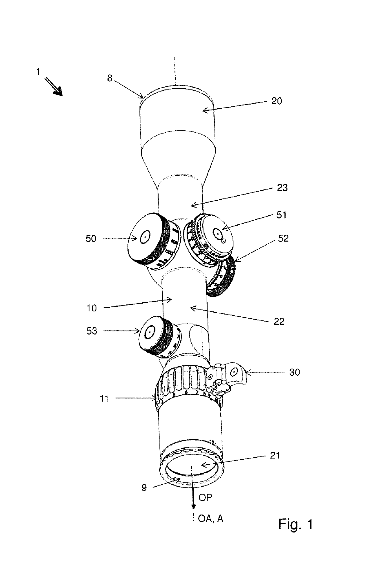
[0047]FIG. 1 shows a rifle scope 1 in a perspective view. This has a housing 10, in which optical lenses 20, 21, 22, 23 are arranged along an optical path OP. In particular, the housing 10 is tubular in design and the optical lenses 20, 21, 22, 23 are mounted in the housing 10. Some of the optical lenses 20 form an objective in the region of an entry opening 8 of the housing 10. Others of the optical lenses 21 form an eyepiece in the region of an exit opening 9 of the housing 10. In the middle portion of the tubular housing 10 there are arranged optical lenses 22, 23 which form an inversion system. With these lenses 22, 23, an optical magnification of a target object can also be carried out, since these optical lenses 22, 23 of the inversion system are each mounted movable along the optical path OP in the housing 10.

[0048]In the present case, the optical path OP and an optical axis OA of the rifle scope 1 outside of the latter are congruent or coaxial. Merely by adjustment functions...


PUM


Abstract

The invention concerns a rifle scope (1) with a housing (10), in which optical lenses (20, 21, 22, 23) are arranged along an optical path (OP), and with an adjusting wheel (11) for adjusting a function, wherein the adjusting wheel (11) is mounted so as to turn relative to the housing (10) about an axis of rotation (A), and wherein the adjusting wheel (11) has a first coupling means (13), on which an adjusting aid (30) which projects relative to the axis of rotation (A) radially about the outer circumference (12) of the adjusting wheel (11) is releasably secured to a second coupling means (31).

Description

FIELD OF THE INVENTION[0001]The invention concerns a rifle scope with an adjusting aid.BACKGROUND ART[0002]Rifle scopes are used for hunting and in the military to sight weapons on targets at great distance. For this, they have a lens arrangement along an optical path inside a housing, by which a target object is magnified. In particular, the lens arrangement comprises at least one objective and one eyepiece. The objective is an optical collecting system for real optical imaging of the target object and the eyepiece is a lens system by which one can look into the lens arrangement with one eye.[0003]An intermediate image projected by the objective in a first image plane at the objective side is magnified and projected into a second image plane at the eyepiece side. Large magnifications only allow limited fields of vision, which do not permit an overview of a larger image portion, especially at short range. In order to also effectively include these objects in the sight, there is a va...

Claims


Application Information

Patent Timeline
Patent Type & Authority Patents(United States)
IPC IPC(8): F41G1/38
CPCF41G1/38
Inventor SCHMIDT, MANUEL
Owner SCHMIDT & BENDER
Why Eureka
Try Eureka