Unlock instant, AI-driven research and patent intelligence for your innovation.

Pressurizable sealing element

a sealing element and pressurizable technology, applied in the direction of diaphragm valves, valve details, engine components, etc., can solve the problems of not being able to meet the very specific process needs and requirements with 100 percent reliability, sealing disk damage, and sealing becoming impossibl

Active Publication Date: 2016-03-29
STADLER ACHIM
View PDF27 Cites 2 Cited by
  • Summary
  • Abstract
  • Description
  • Claims
  • Application Information

AI Technical Summary

Benefits of technology

The solution effectively seals large radial gaps and deformed pipes, maintaining reliability under high pressures (10-80 bars) and allowing for easy removal after repair, enhancing process reliability and safety.

Problems solved by technology

In case of equipment which may be used for performing the hot-tapping or line-stopping method, respectively, common elastomeric sealing disks are usually used, none of them, however, being able to fulfill the very specific process needs and requirements with 100 percent reliability.
As a result thereof, the sealing disk may be damaged to an extent where sealing becomes impossible.
Meanwhile, it has been found that a very large radial gap between the plugging head (plug) and the inner pipeline wall of 20 mm or more cannot be sealed completely by using known approaches, and that process-reliability can therefore not be ensured.
Considerably deformed cylindrical pipes of oval cross section cannot be sealed process-reliably by the annular sealing disk mounted to the plugging head, since it is in fact their oval shape which leaves relatively large gaps that cannot be bridged or sealed by a circular sealing disk.
Moreover, it has been found that malleable sealing elements which have been used in known approaches are partly or completely undercut by the pressure to be shut off, and that it becomes impossible to dismount the whole sealing structure including the plugging head from the sealed flow section due to the constantly applied pressure which is to be shut off.

Method used


Image

  • Pressurizable sealing element
  • Pressurizable sealing element
  • Pressurizable sealing element

Examples


second embodiment

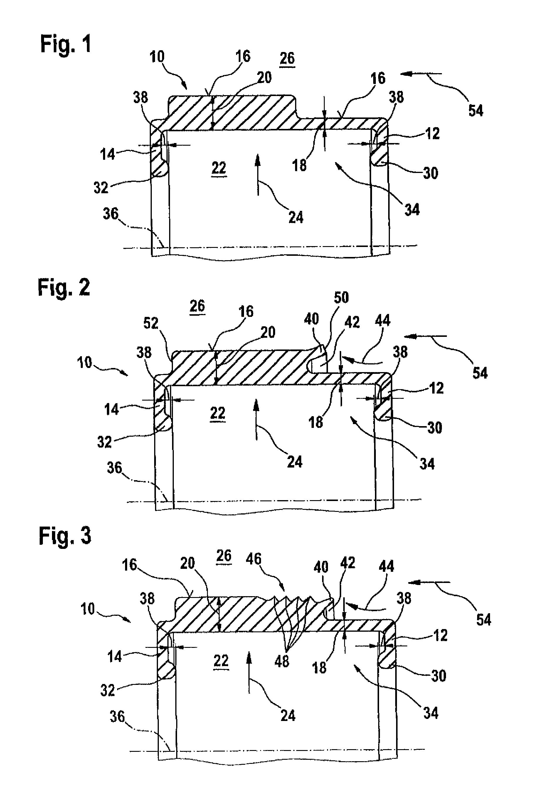
[0011]As a modification of this other, second embodiment of the pressurizable sealing element proposed according to the present invention, the portion of the molded seal configured to have a larger wall thickness may be provided with a plurality of cascading sealing lips which are arranged in a row, and which implement the sealing effect.

fourth embodiment

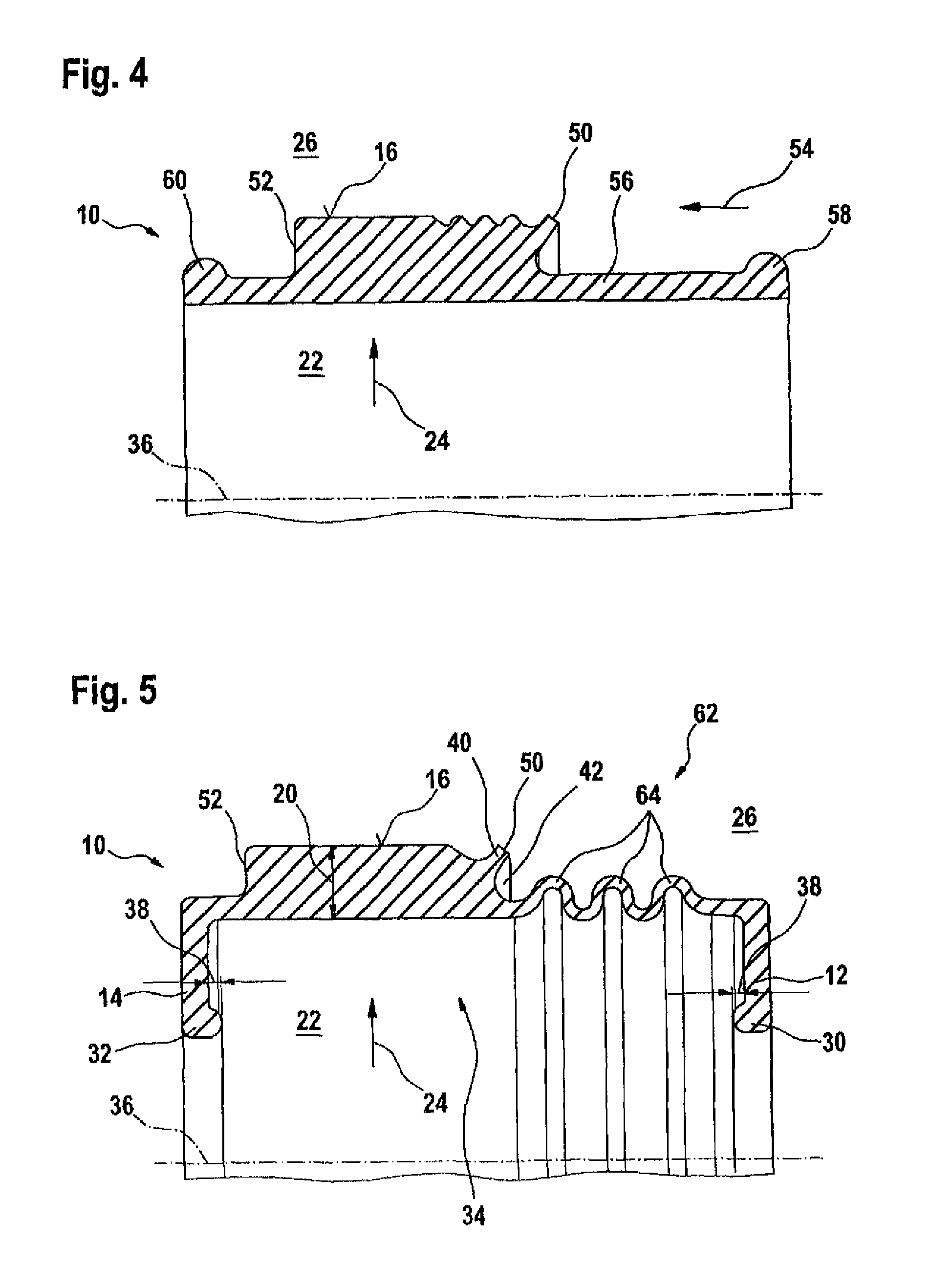
[0012]In another, fourth embodiment of the pressurizable sealing element proposed according to the invention, the bead-like thickenings of the lateral surface are configured to form the static sealing beads which extend in a radial direction. In this case, the pressurizable sealing element proposed according to the present invention is not U-shaped, but is rather of a sleeve-type which is formed without end faces, wherein the bead-like thickenings in the three preceding embodiments, which are adapted to fix the pressurizable sealing element, are located at the ends of the lateral surfaces of the sleeve-like sealing element.

[0013]In another, fifth embodiment of the idea underlying the present invention, the pressurizable sealing element is configured to have a swellable spring which is similar to a bellows. This swellable spring extends in the lateral surface of the pressurizable sealing element proposed according to the present invention in a wave-like or zigzag-like arrangement, fo...

first embodiment

[0022]FIG. 1 shows the pressurizable sealing element proposed according to the invention having lateral surface regions of differing wall thickness,

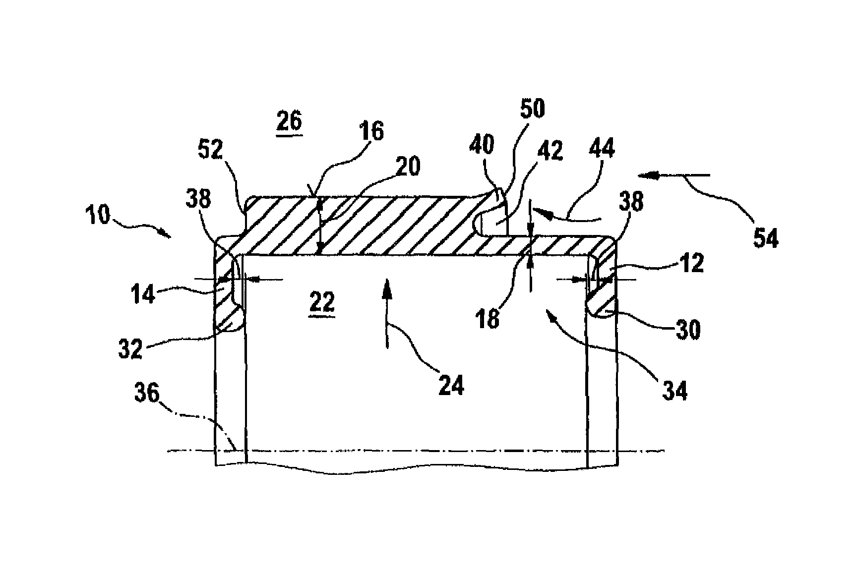
[0023]FIG. 2 shows a second embodiment of the pressurizable sealing element proposed according to the invention having a deflectable sealing lip formed in a lateral surface region,


PUM


Abstract

The invention relates to a sealing element (10) to be mounted on a plugging head (76). The plugging head (76) is introduced into an access opening in the pipeline (70) or pipe (70). The pressurizable sealing element (10) delimits at least one pressurizable cavity (22, 92) with an inner surface (78), and seals an inner wall (74) of the pipeline (70) or pipe (70) with a generated surface (16, 40, 46, 48) when a pressure pi is applied to the cavity (22, 92).

Description

CROSS REFERENCE TO RELATED APPLICATIONS[0001]This application is the National Stage of PCT / EP2009 / 004046 filed on Jun. 5, 2009. The international application under PCT article 21(2) was not published in English.TECHNICAL FIELD[0002]The present invention refers to a pressurizable sealing element made of an elastomeric material, for example for securely plugging pressurized pipes for conducting media, such as oil or gas pipes, or even water pipes.TECHNICAL BACKGROUND[0003]Special plugs which may be part of a plugging head may be used for repairing pipelines or pipes which may conduct pressurized media such as oil, gas or even water. The plugging head is part of a hot-tapping equipment for repairing pressurized pipelines, for example. Hot tapping means drilling in a pressurized state and is a method adapted for drilling a hole in a pressure-conducting body and for forming a branching or bypass or bypass line in case of pipe portions which have to be repaired or even replaced. The hot-t...

Claims


Application Information

Patent Timeline
Patent Type & Authority Patents(United States)
IPC IPC(8): F16K7/02F16K7/10
CPCF16K7/02F16K7/10
Inventor STADLER, ACHIMBARTH, ARMIN
Owner STADLER ACHIM