Eureka AIR delivers breakthrough ideas for toughest innovation challenges, trusted by R&D personnel around the world.

Communication device, noise removing method, and program

Inactive Publication Date: 2009-10-15
SONY CORP
View PDF5 Cites 28 Cited by
  • Summary
  • Abstract
  • Description
  • Claims
  • Application Information

AI Technical Summary

Benefits of technology

[0019]By this configuration, an external noise can be stably removed from a transmission signal where a spectrum spread signal is modulated.
[0052]According to the embodiments of the present invention described above, an external noise can be stably removed from a transmission signal where a spectrum spread signal is modulated.

Problems solved by technology

Meanwhile, the electronic apparatus that has a GPS function has had multifunction and high performance, and unnecessary radiation that is generated in the electronic apparatus has increased.
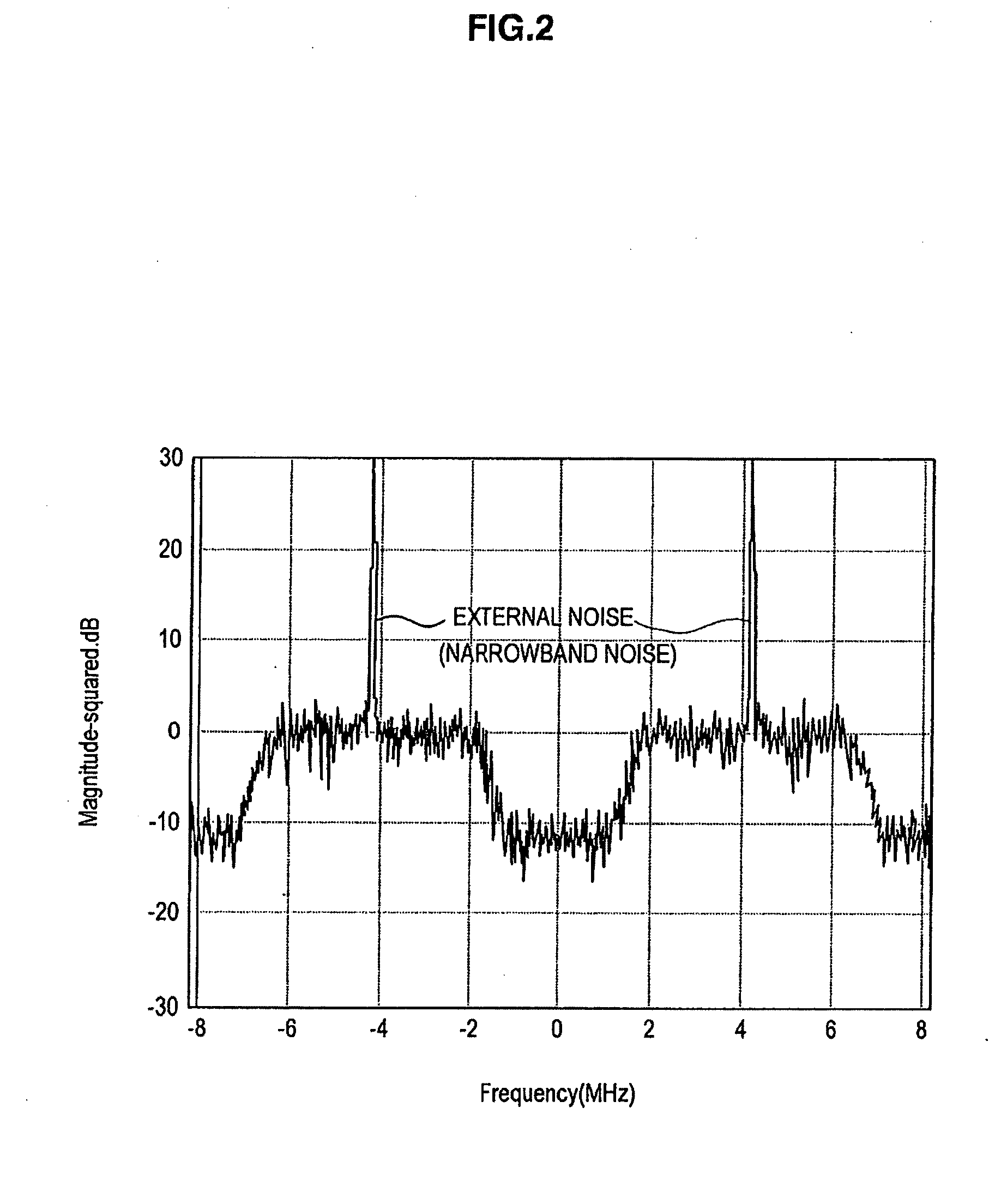
However, when the external noise is stronger than the normal thermal noise that is generated in the GPS receiving device, reception sensitivity is deteriorated by the amount exceeding the level of the normal thermal noise.
That is, in the communication device where the technology for removing an external noise according to the related art is applied, an unstable operation, such as divergence, may be generated depending on setting of the control loop or a signal (signal used to remove the external noise) input to the notch filter.
Accordingly, the communication device using the technology for removing an external noise according to the related art cannot stably remove the external noise.
Even though the technologies according to the related art are combined, it may not be possible to stably remove the external noise.
However, since the above countermeasure affects a design or cost of the communication device (or electronic apparatus where the communication device is mounted), the above countermeasure is not preferable.

Method used


Image

  • Communication device, noise removing method, and program
  • Communication device, noise removing method, and program
  • Communication device, noise removing method, and program

Examples


first embodiment

(Program )

[0187]The external noise can be stably removed from the transmission signal where the spectrum spread signal is modulated, by using a program that allows a computer to function as the noise removing unit 106 of the communication device 100 according to the first embodiment.

(Noise Removing Method According to a First Embodiment)

[0188]Next, a noise removing method according to the first embodiment will be described. FIG. 11 is a flowchart illustrating a noise removing method according to a first embodiment of the present invention. In the description below, the noise removing method shown in FIG. 11 is executed by the communication device 100 (specifically, noise removing unit 106).

[0189]The communication device 100 performs a fast Fourier transform on the discretization signal (S100). In this case, the communication device 100 can periodically or randomly execute a process of Step S100. Further, the process may be executed whenever the discretization signal is input.

[0190]B...

second embodiment

(Program )

[0213]The external noise can be stably removed from the transmission signal where the spectrum spread signal is modulated, by using a program that allows a computer to function as the noise removing unit 202 of the communication device 200 according to the second embodiment.

(Noise Removing Method According to a Second Embodiment)

[0214]Next, a noise removing method according to a second embodiment will be described. FIG. 14 is a flowchart illustrating a noise removing method according to a second embodiment of the present invention. In the description below, the noise removing method shown in FIG. 14 is executed by the communication device 200 (specifically, noise removing unit 202).

[0215]The communication device 200 performs a fast Fourier transform on the discretization signal, and derives a power spectrum based on the result of the fast Fourier transform (S200).

[0216]If the power spectrum is derived in Step S200, the communication device 200 outputs a discretization sign...

third embodiment

(Program )

[0236]The external noise can be stably removed from the transmission signal where the spectrum spread signal is modulated, by using a program that allows a computer to function as the noise removing unit 302 of the communication device 300 according to the third embodiment.

(Noise Removing Method According to a Third Embodiment)

[0237]Next, a noise removing method according to a third embodiment will be described. FIG. 17 is a flowchart illustrating a noise removing method according to a third embodiment of the present invention. In the description below, the noise removing method shown in FIG. 17 is executed by the communication device 300 (specifically, noise removing unit 302).

[0238]Similar to Step S100 of FIG. 11, the communication device 300 performs a fast Fourier transform on the discretization signal y(t) (S300). In addition, similar to Step S200 of FIG. 14, the communication device 300 derives a power spectrum Py(n) based on the result Y(n) of the fast Fourier trans...


PUM


Abstract

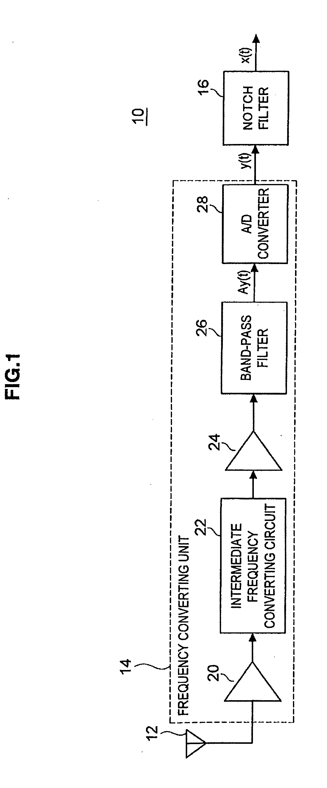
A communication device according to an embodiment of the present invention includes a communication antenna that receives a transmission signal where a spectrum spread signal subjected to a spectrum spread is modulated; an intermediate frequency converting unit that converts the transmission signal received by the communication antenna into an intermediate frequency signal having a predetermined frequency; an analog to digital converting unit that discretizes the intermediate frequency signal and outputs a discretization signal; a noise removing unit that detects a noise other than a normal thermal noise included in the discretization signal and removes the detected noise from the discretization signal; and a demodulating unit that demodulates the spectrum spread signal, based on the discretization signal that is output from the noise removing unit.

Description

CROSS REFERENCES TO RELATED APPLICATIONS[0001]The present invention contains subject matter related to Japanese Patent Application JP 2008-044496 filed in the Japan Patent Office on Feb. 26, 2008, the entire contents of which being incorporated herein by reference.BACKGROUND OF THE INVENTION[0002]1. Field of the Invention[0003]The present invention relates to a communication device, a noise removing method, and a program.[0004]2. Description of the Related Art[0005]In recent years, a GPS (Global Positioning System) function is mounted in various electronic apparatuses, such as a car navigation device, a portable communication device like a mobile phone, or a digital still camera. The electronic apparatus includes a GPS receiving device (an example of a communication device) that receives a transmission signal called a GPS L1 C / A code signal that is transmitted from four or more GPS satellites and specifies a position based on the received transmission signal or functions as a GPS re...

Claims


Application Information

Patent Timeline
IPC IPC(8): H04B1/69H04B1/707H04B1/10H04B1/71
CPCG01S19/13G01S19/21H04B1/1036H04B1/7097H04B1/7101H04B2201/70715H04B1/707H04B1/10
Inventor TANAKA, KATSUYUKITAKAHASHI, HIDEKI
Owner SONY CORP
Why Eureka
Eureka Blog
Learn More