
Stray-light-coupled biometrics sensing module and electronic apparatus using the same

a biometrics and sensing module technology, applied in the field of straylight-coupled biometrics sensing modules and electronic devices, can solve the problems of inability the outlook of the electronic apparatus is affected, and the capacitive sensor cannot be used to sense the wet finger or the sensing surface with liquid

Active Publication Date: 2016-03-29
J METRICS TECH CO LTD
View PDF20 Cites 12 Cited by
  • Summary
  • Abstract
  • Description
  • Claims
  • Application Information

AI Technical Summary

Benefits of technology

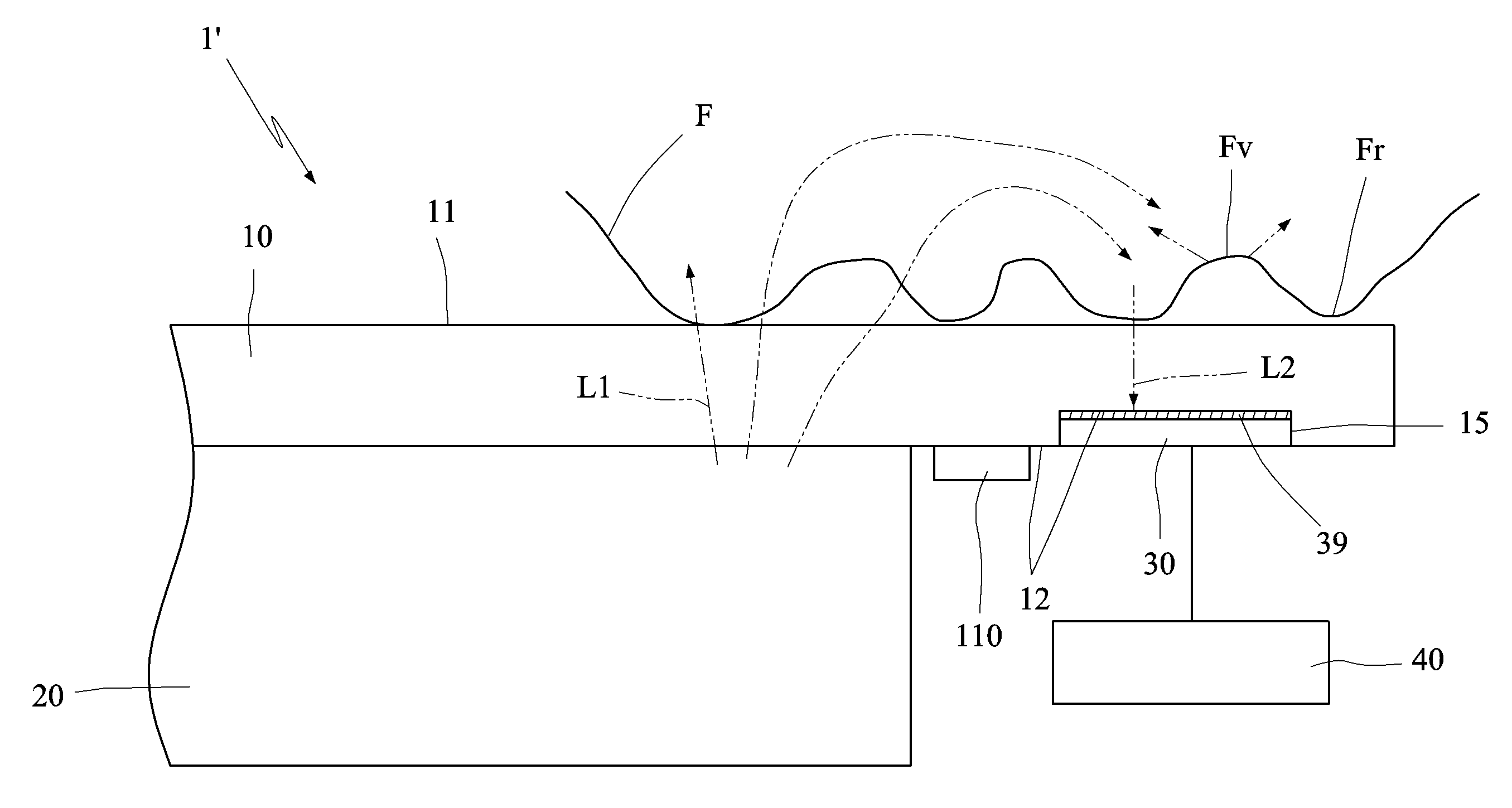
The invention provides a stray-light-coupled biometrics sensing module and an electronic apparatus using the same. This allows for effective optical fingerprint sensing using the light source of the display, without affecting the appearance of the electronic apparatus or causing discomfort to the user. The use of stray light in the sensing module avoids the need for an additional light source and allows for different wavelengths of light rays to be used for sensing.

Problems solved by technology

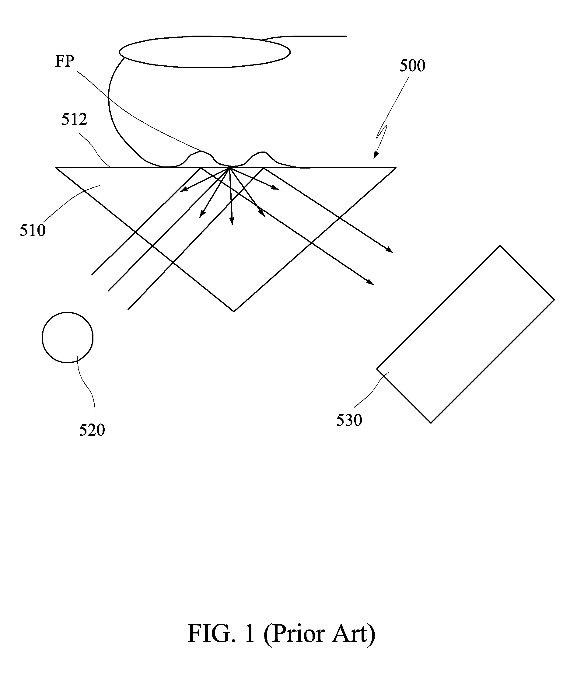
The conventional fingerprint sensors are mainly classified into a capacitive sensor and an optical sensor, wherein the maximum drawback of the capacitive sensor is that it cannot be used to sense the wet finger or the sensing surface with the liquid.
So, the outlook of the electronic apparatus is affected, and the dust and dirtiness may be left in the gap between the sensor module and the electronic apparatus, and the outlook is further deteriorated.
This sensing principle has the maximum drawback that the dry finger cannot be sensed to have the good continuity texture image, so that the misreading problem occurs when the minutia points are being extracted.
This also increases the cost and the design complexity.

Method used


Image

  • Stray-light-coupled biometrics sensing module and electronic apparatus using the same
  • Stray-light-coupled biometrics sensing module and electronic apparatus using the same
  • Stray-light-coupled biometrics sensing module and electronic apparatus using the same

Examples


Embodiment Construction

[0024]The present invention will be apparent from the following detailed description, which proceeds with reference to the accompanying drawings, wherein the same references relate to the same elements.

[0025]The invention is to eliminate the drawbacks of the capacitive and the conventional optical fingerprint sensing methods. First, the sensor is hidden to provide a beautiful design ID and overcome the problem of sensing the wet finger. Second, the stray light sensing principle is adopted to replace the conventional total reflection principle of the collimated light and to serve as the optical sensing basis to overcome the problem of sensing the dry finger. Third, the sensing module does not have the light source, so that the complexity and difficulty in design are decreased.

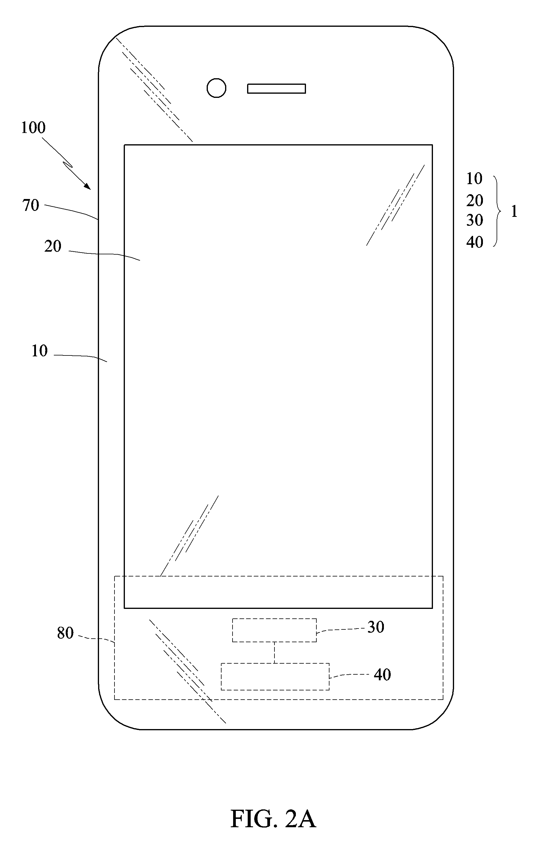
[0026]FIGS. 2A to 2C show outlooks of electronic apparatuses of three examples according to a preferred embodiment of the invention. As shown in FIG. 2A, the electronic apparatus 100 of this example is a mobile ...


PUM


Abstract

A stray-light-coupled biometrics sensing module includes a light-transparent body, a display unit and an optical module. The light-transparent body has a front side and a backside. The front side is configured to support an organic object thereon. The display unit attached to the backside of the light-transparent body displays a frame. The optical module is attached to the backside of the light-transparent body through an adhesive, and is disposed adjacent to the display unit. First light rays of the frame emitted from an eye-viewing screen couple into the organic object through the light-transparent body. After travelling a short distance in the organic object, the first light rays couple out of the organic object and re-enter the light-transparent body as second light rays entering the optical module. The optical module senses the second light rays to generate a biometrics image signal. An electronic apparatus is also disclosed.

Description

[0001]This application claims priority of No. 101148214 filed in Taiwan R.O.C. on Dec. 19, 2012 under 35 USC 119, the entire content of which is hereby incorporated by reference.BACKGROUND OF THE INVENTION[0002]1. Field of the Invention[0003]The invention relates to a stray-light-coupled biometrics sensing module and an electronic apparatus using such biometrics sensing module.[0004]2. Related Art[0005]Recently, portable mobile apparatuses, such as mobile phones, tablet computers and the like, are developed in rising manners and have become indispensable appliances in the life. More particularly, with the development of the network and the electronic commerce requirement, the mobile phone may further be integrated with an authentication function, representing the personal identification, such as that of an electronic identification card, an electronic passport, a consumable chip card and the like. Therefore, in addition to the conventional digital password authentication, it is a fu...

Claims


Application Information

Patent Timeline
Patent Type & Authority Patents(United States)
IPC IPC(8): G06K9/00G06F3/042
CPCG06F3/042G06K9/00026G06K2009/0006G06V40/1341G06V40/1335
Inventor CHOU, BRUCE, C., S.
Owner J METRICS TECH CO LTD
Learn More