
Method and system for automatically determining a localizer in a scout image

a technology of automatic determination and localizer, applied in the field of medical examinations, can solve the problems of difficult to ensure the accuracy of the location, difficult to obtain an accurate scan range, and manual operation is not only laborious and time-consuming, so as to simplify the workflow of medical examinations, avoid time-consuming and laborious manual operations, and improve the efficiency of medical examinations

Active Publication Date: 2016-03-29
GE MEDICAL SYST GLOBAL TECH CO LLC
View PDF5 Cites 2 Cited by
  • Summary
  • Abstract
  • Description
  • Claims
  • Application Information

AI Technical Summary

Benefits of technology

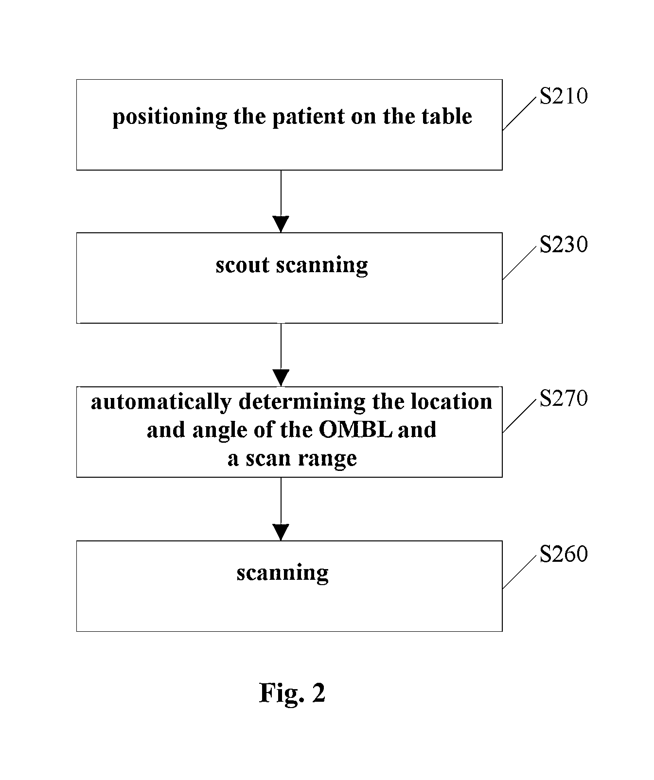
This approach simplifies and improves the accuracy of scan alignment, reducing manual labor and minimizing unnecessary scans, thereby enhancing the efficiency and performance of medical examinations while reducing X-ray exposure.

Problems solved by technology

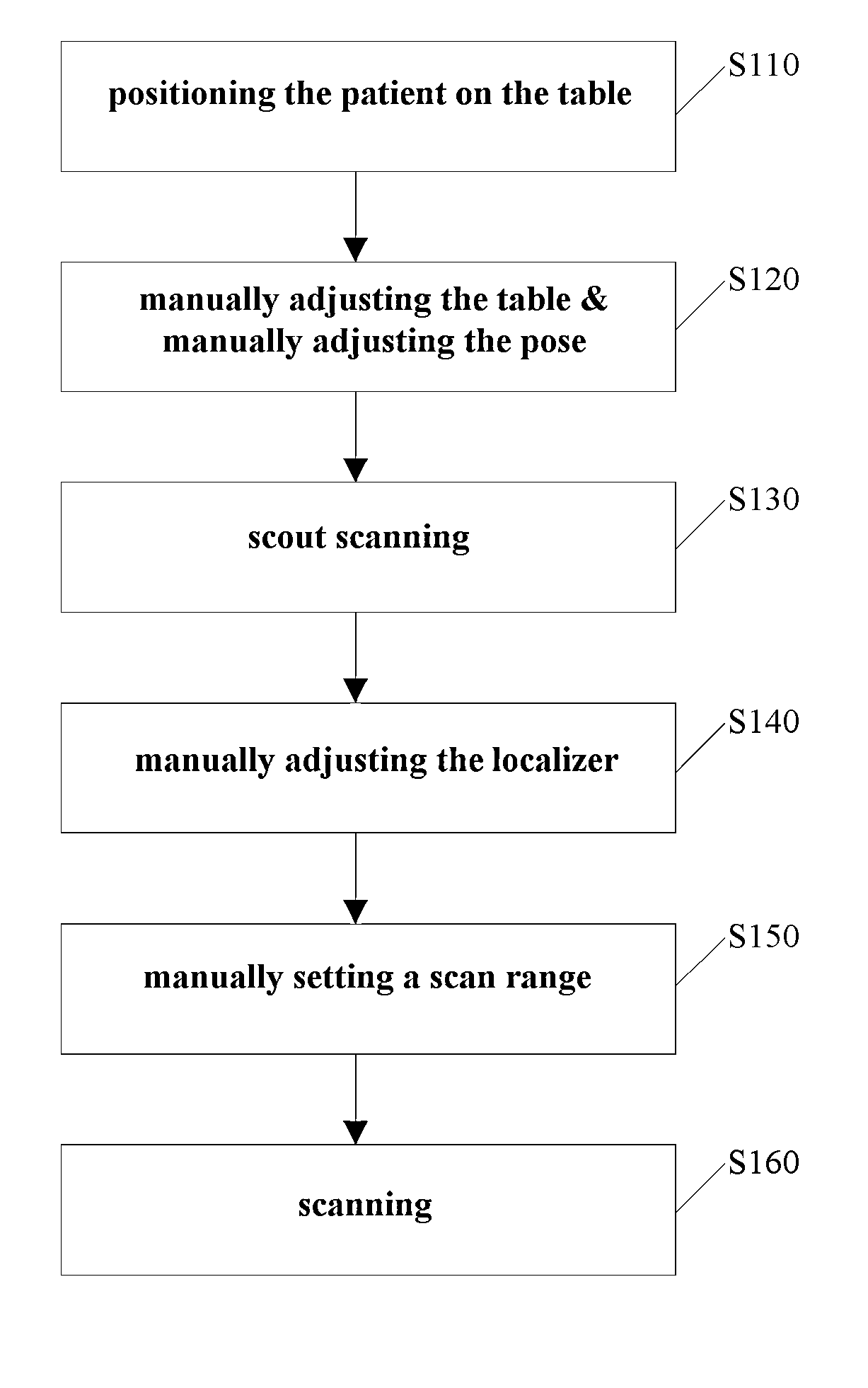
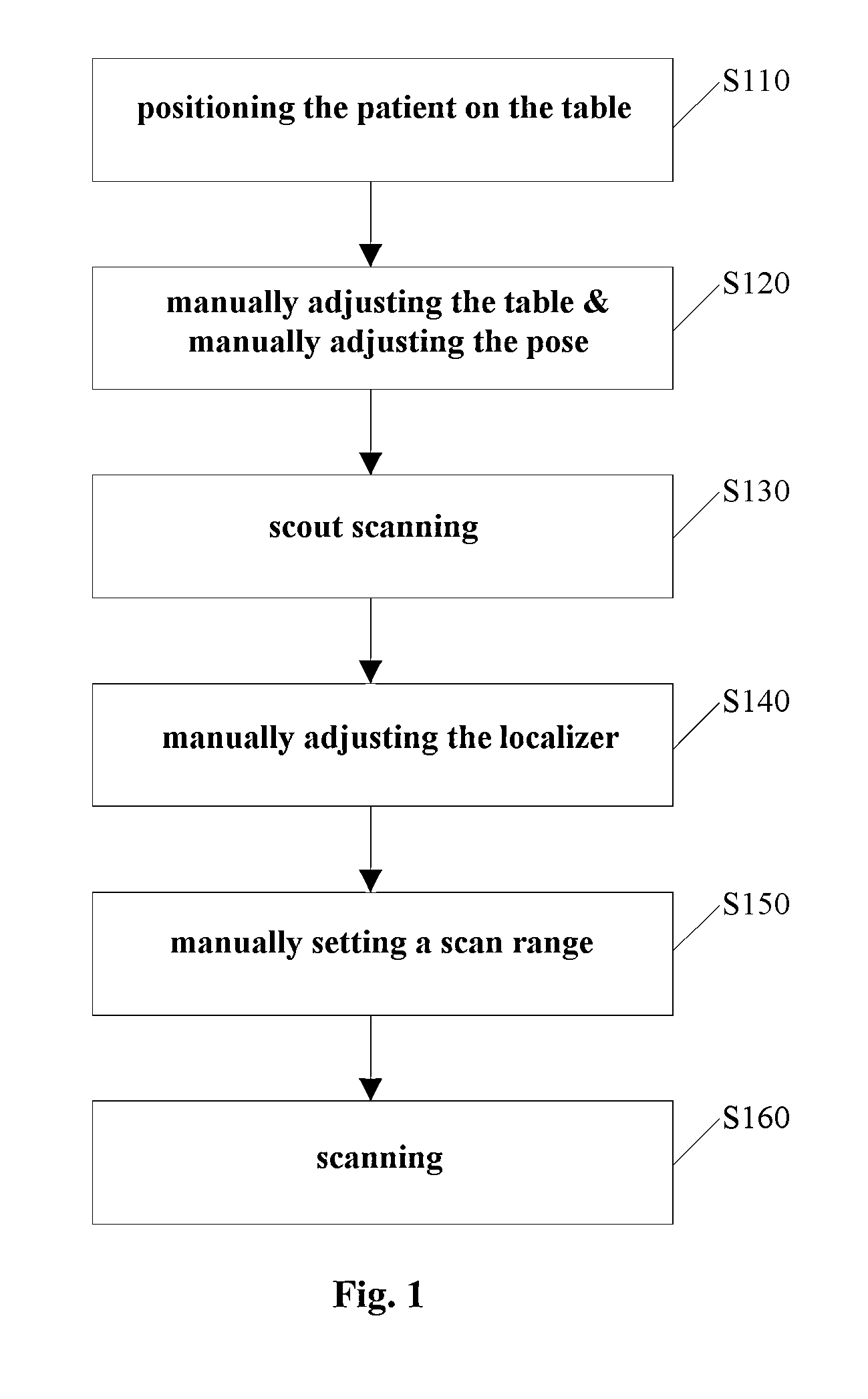
However, the current provision of a localizer is essentially achieved by manual operations of an operator, which is not only laborious and time-consuming, but also difficult to ensure precision of the location and angle of the localizer, such that it is difficult to obtain an accurate scan range.
Be it manually adjusting the head pose of the patient so as to enable the OMBL of the patient to fit the laser line, or manually tilting the CT gantry so as to enable the laser line to fit the OMBL of the patient, said manual operation is not only laborious and time consuming, but also difficult to fulfill an accurate OMBL alignment.
Current typical workflows for a complete head CT scan are subject to the following problems: manual alignment of the laser line or the scan plane to the OMBL is laborious and time consuming; manual alignment of the laser line or the scan plane to the OMBL may be inaccurate if the operator is not familiar with the operation; the OMBL angle is sometimes too inclined to the eyes, resulting in an unnecessary part of eyeballs being scanned; and the OMBL angle is sometimes too inclined to the cerebellum or is translated to the cerebellum, resulting in part of the brain tissue being missed, such that a repeated scan or complementary scan may be clinically needed.
However, image registration is not suitable for indistinct scout images, such as scout images of the head.
Therefore, up to now, there is no appropriate image registration method successfully applicable to automatic detection and location of the OMBL in CT scout images.

Method used


Image

  • Method and system for automatically determining a localizer in a scout image
  • Method and system for automatically determining a localizer in a scout image
  • Method and system for automatically determining a localizer in a scout image

Examples


Embodiment Construction

[0047]Embodiments of the present invention described herein are illustrated by way of example and not by way of limitation in the accompanying figures. For simplicity and clarity of illustration, elements illustrated in the figures are not necessarily drawn to scale. For example, the dimensions of some elements may be exaggerated relative to other elements for clarity. Further, where considered appropriate, reference numerals have been repeated among the figures to indicate corresponding or analogous elements. Reference in the specification to “one embodiment” or “an embodiment” of the invention means that a particular feature, structure, or characteristic described in connection with the embodiment is included in at least one embodiment of the invention. Thus, the appearances of the phrase “in one embodiment” in various places throughout the specification are not necessarily all referring to the same embodiment.

[0048]The present invention will be described in detail with an example...


PUM


Abstract

A method and system for automatically determining a localizer in a scout image. The method comprises obtaining a 3D model best matched to an object to be scanned and projecting a localizer in the best matched 3D model onto a scout image of the object to be scanned to obtain an optimal localizer. The system comprises an obtaining device for obtaining a 3D model best matched to an object to be scanned and a determining device for projecting a localizer in the best matched 3D model onto a scout image of the object to be scanned to obtain an optimal localizer.

Description

TECHNICAL FIELD[0001]The present disclosure relates to the field of medical examinations, and in particular, to method and system for automatically determining a localizer in a scout image for medical examinations.BACKGROUND ART[0002]In the field of medical examinations, such as in a computerized tomography (CT) or nuclear magnetic resonance (MR) examination, a scan range normally needs to be determined. This can be achieved by acquiring a scout image of the object to be scanned and providing a suitable localizer therein. However, the current provision of a localizer is essentially achieved by manual operations of an operator, which is not only laborious and time-consuming, but also difficult to ensure precision of the location and angle of the localizer, such that it is difficult to obtain an accurate scan range.[0003]The following takes a complete head CT scan as an example to illustrate the existing workflows.[0004]For a complete head CT scan, current workflows are mainly depende...

Claims


Application Information

Patent Timeline
Patent Type & Authority Patents(United States)
IPC IPC(8): G06K9/00G06T7/00
CPCG06T7/0032G06T2200/04G06T2207/10081G06T2207/10088G06T2207/30016G06T7/344
Inventor LIU, PINGDONG, JIAQINSHI, YILUN
Owner GE MEDICAL SYST GLOBAL TECH CO LLC
Learn More