
Frequency dependent dual solid-state and vacuum tube power amplifier-section instrument amplifier

a technology of vacuum tube power amplifiers and solid-state amplifiers, which is applied in the direction of amplifiers, low-frequency amplifiers, instruments, etc., can solve the problems of less desirable sound quality, more ‘harsh’, and more energy, and achieve the effect of pleasing and musical

Inactive Publication Date: 2016-04-05
ROBLING JASON O
View PDF6 Cites 5 Cited by
  • Summary
  • Abstract
  • Description
  • Claims
  • Application Information

AI Technical Summary

Benefits of technology

This patent aims to provide an amplifier with improved sound and versatility. It achieves this by allowing the musician to adjust the frequency range and balance between two power sections. This results in a pleasing and musical result, or timbre, of the two power sections, where the fundamental is tight, clear, and loud, and the overtones are smooth, warm, and round. Additionally, the patent suggests adding a blend potentiometer to blend the two power sections across the whole frequency range of their instrument or a balance potentiometer to adjust for slight differences in volume taper between the two power-amp sections as the amplifier is turned up or down. This would allow the musician to switch between full-range amplification using the solid-state section or the tube power section depending on the situation.

Problems solved by technology

This is not however, what creates the desirable ‘tube’ sound that most musicians prefer.
However, many musicians that play electric instruments capable of producing lower bass frequencies, such as the electric bass-guitar or keyboard, will often use amplifiers with completely solid-state power sections for mainly two reasons: First, for a tube amp to reproduce and amplify bass frequencies with enough volume without clip (distortion) requires more energy, weight, and expensive hardware, than from a solid-state power amplifier.
Second, many of these same musicians do prefer the clean, loud, and ‘tight’ sound of low / bass frequencies through a solid-state amplifier, but as they move upward into the middle and higher frequencies on the instrument, the sound quality becomes less desirable, or more ‘harsh,’ due to the inherent sonic qualities of solid-state amplification.

Method used


Image

  • Frequency dependent dual solid-state and vacuum tube power amplifier-section instrument amplifier
  • Frequency dependent dual solid-state and vacuum tube power amplifier-section instrument amplifier
  • Frequency dependent dual solid-state and vacuum tube power amplifier-section instrument amplifier

Examples


Embodiment Construction

[0014]The drawings are for the purpose of illustrating the inventor's preferred embodiments and not for the purpose of limiting the invention.

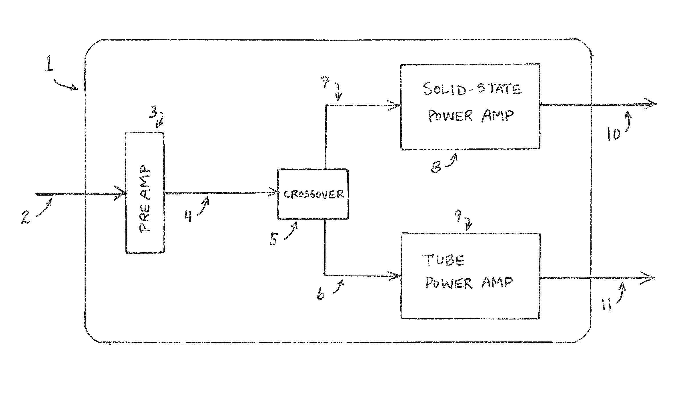
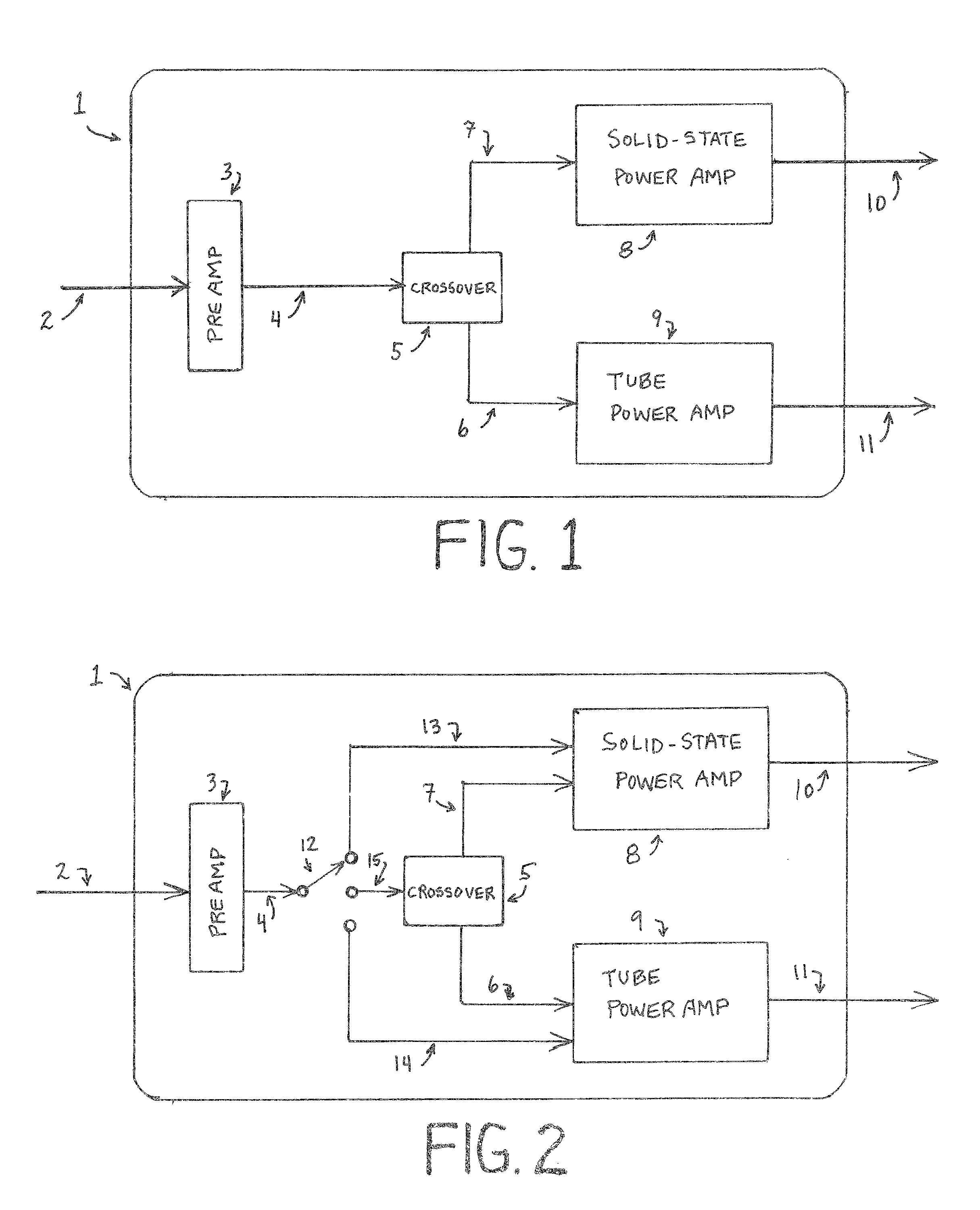
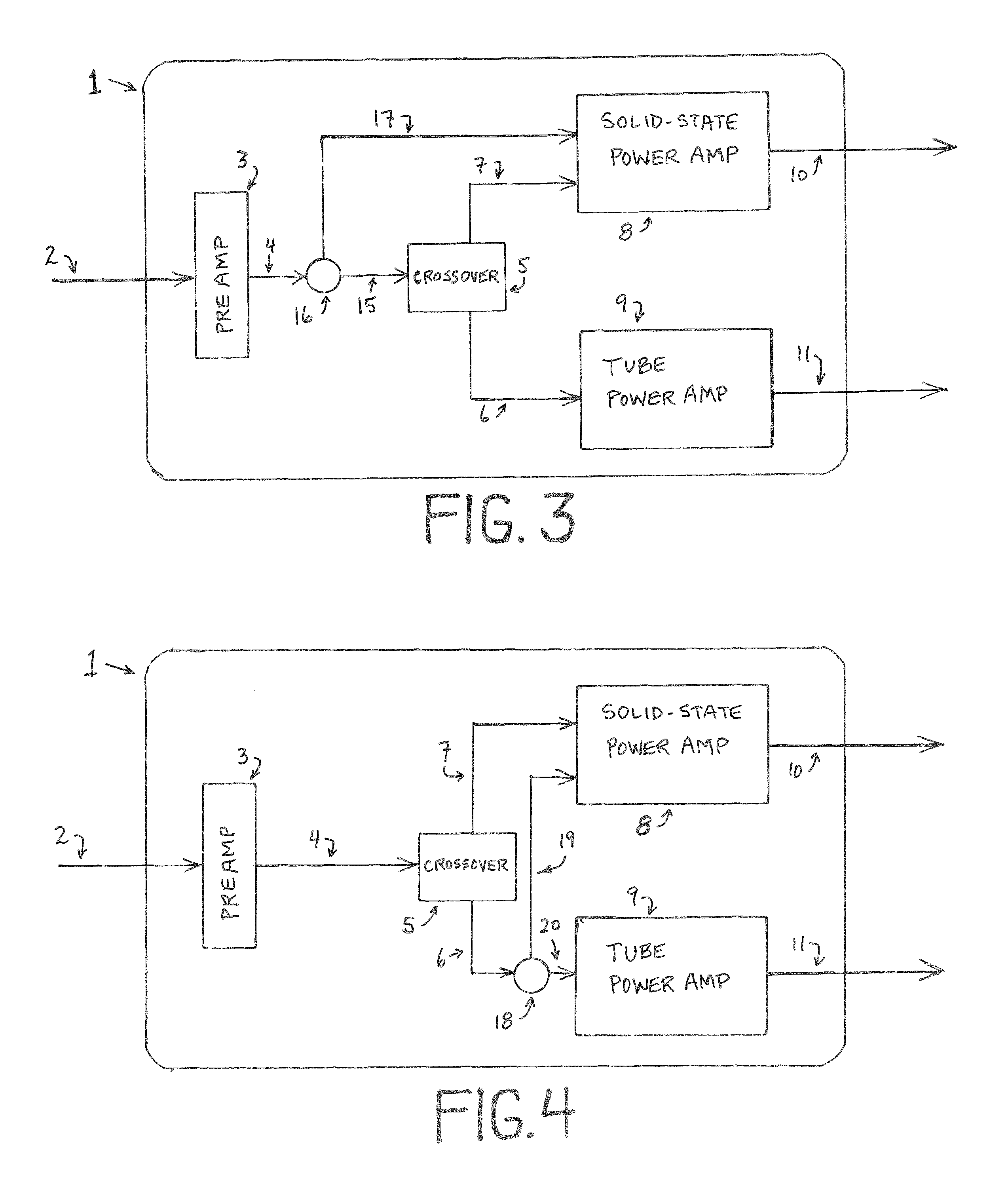
[0015]FIG. 1 shows the amplifier 1, which includes the preamp 3, active 2-way crossover 5, solid-state power amplifier 8, and tube power amplifier 9. The audio input from a musical instrument is shown 2, enters the preamp, where pre-amplification and equalization occur, and other processes such as limiting and / or compression may also take place. The audio 4, leaves the preamp and goes to the crossover 5, where audio frequencies below the crossover point are sent to the solid-state power amp 8, via signal path 7. Signal path 4 is where a common effects-loop and / or direct-out would be located. Audio frequencies above the crossover point are sent to the tube power amp 9, via signal path 6. The outputs 10 and 11 are sent to external loudspeakers.

[0016]FIG. 2 shows the addition of a switch 12 which allows the selection of sending the full-range aud...


PUM


Abstract

An audio amplifier apparatus and method which has a preamp, active 2-way crossover, solid-state power amplifier, and tube power amplifier. Audio input from a musical instrument enters the preamp where pre-amplification, equalization, and other processes such as limiting or compression take place. Audio leaves the preamp and goes to a crossover, wherein frequencies below a crossover point are sent to a solid-state power amp via a first signal path, and wherein audio frequencies above the crossover point are sent to a tube power amp via a second signal path. Outputs from the solid-state power amp and tube power amp are sent to external or internal loudspeakers.

Description

[0001]This application claims the benefit of U.S. Provisional Application No. 61 / 671,840 filed Jul. 16, 2012, which is hereby incorporated by reference in its entirety as if fully set forth herein.SUMMARY OF THE INVENTION[0002]The present invention is a self-contained musical instrument amplifier that enables the musician to take advantage of both solid-state and vacuum-tube power amp technology, simultaneously.[0003]The topology of the amplifier is as follows: The mono audio input from an instrument, such as an electric bass guitar, is plugged into the amplifier's pre-amp section. The signal then feeds an internal active 2-way crossover, which is a device used in various audio applications to split the audio signal depending on a preset or selectable frequency point. In this application, all frequencies below the crossover point are sent to the solid-state power-amp section, and all frequencies above the crossover point are sent to the tube power-amp section. The outputs of these t...

Claims


Application Information

Patent Timeline
Patent Type & Authority Patents(United States)
IPC IPC(8): H03F99/00H03F3/181
CPCH03F3/181H03F5/00H03F2200/03H03F2200/411G10H3/187
Inventor ROBLING, JASON O.
Owner ROBLING JASON O
Learn More