Eureka AIR delivers breakthrough ideas for toughest innovation challenges, trusted by R&D personnel around the world.

Noise reduction apparatus and noise reduction method

a technology of noise reduction apparatus and noise reduction method, which is applied in the direction of color television details, television system details, television systems, etc., can solve the problem of not taking into account the variance of noise itself, and achieve the effect of improving the signal to noise ratio and being easily perceived

Active Publication Date: 2016-04-05
CANON KK
View PDF11 Cites 1 Cited by
  • Summary
  • Abstract
  • Description
  • Claims
  • Application Information

AI Technical Summary

Benefits of technology

[0011]The present invention has been made in view of the above-mentioned conventional examples, and provides a noise reduction apparatus and a noise reduction method that improve the signal to noise (S / N) ratio, and process a moving image so that noise is not easily perceived in the moving image, while suppressing a noise component of a frequency band that is easily perceived by the human eye, based on a captured video image, a temporal characteristic of noise, and a time response characteristic of vision.
[0014]With the present invention, a filter is designed so as to improve the S / N ratio, while suppressing a noise component of a frequency band that is easily perceived by the human eye, based on a captured video image, a temporal characteristic of noise, and a time response characteristic of vision. According to the present invention, it is possible to perform noise reduction processing that is adaptive to a temporal characteristic of noise that is different for each image capture and by which noise is not easily perceived.

Problems solved by technology

With the conventional techniques described in Japanese Patent Laid-Open No. 2003-333370 and Japanese Patent Laid-Open No. 2010-147774, there is a problem in that, although adaptive noise reduction is performed on an object or image processing, variance of the noise itself is not taken into consideration.

Method used


Image

  • Noise reduction apparatus and noise reduction method
  • Noise reduction apparatus and noise reduction method
  • Noise reduction apparatus and noise reduction method

Examples


embodiment 1

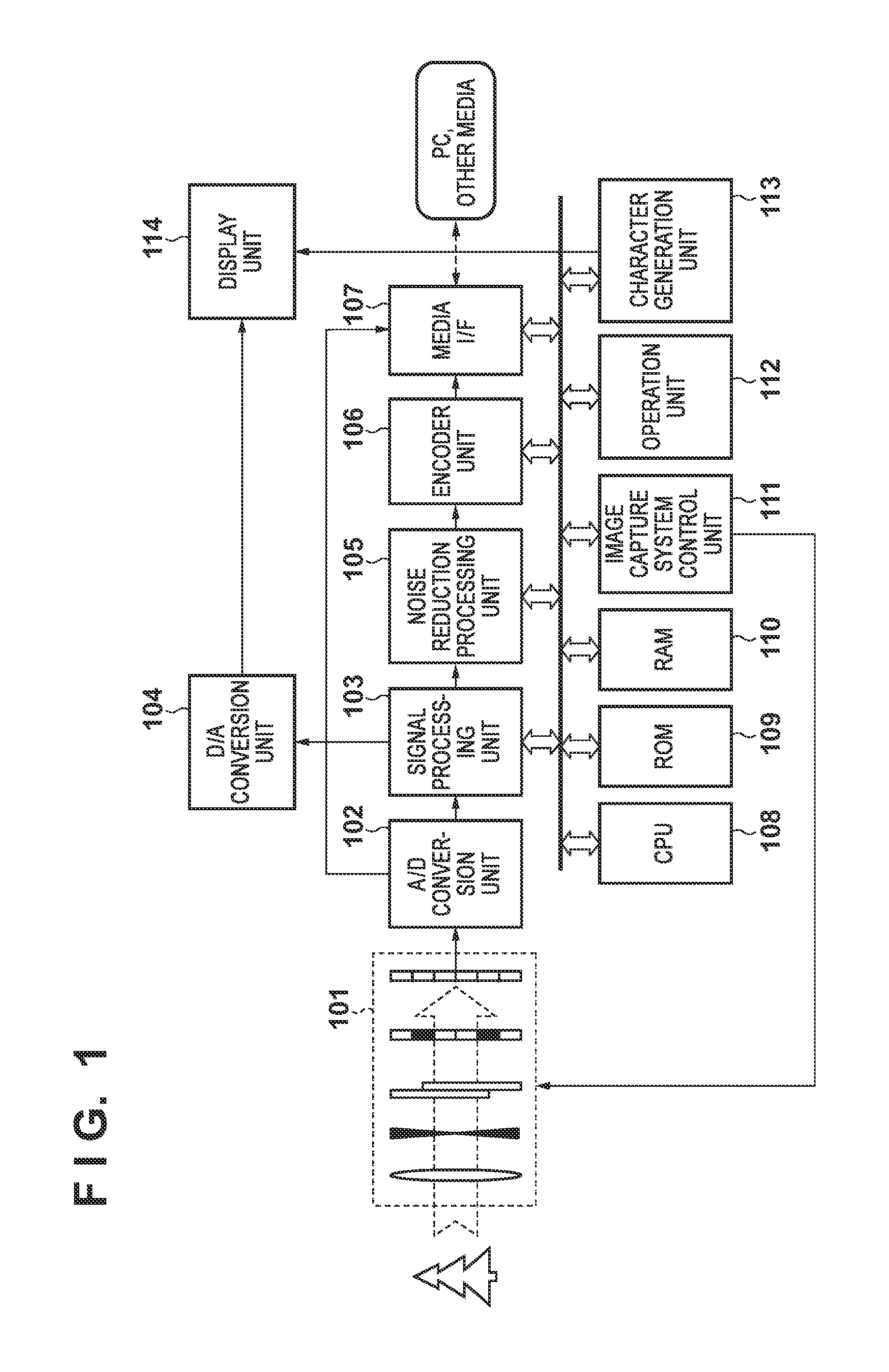
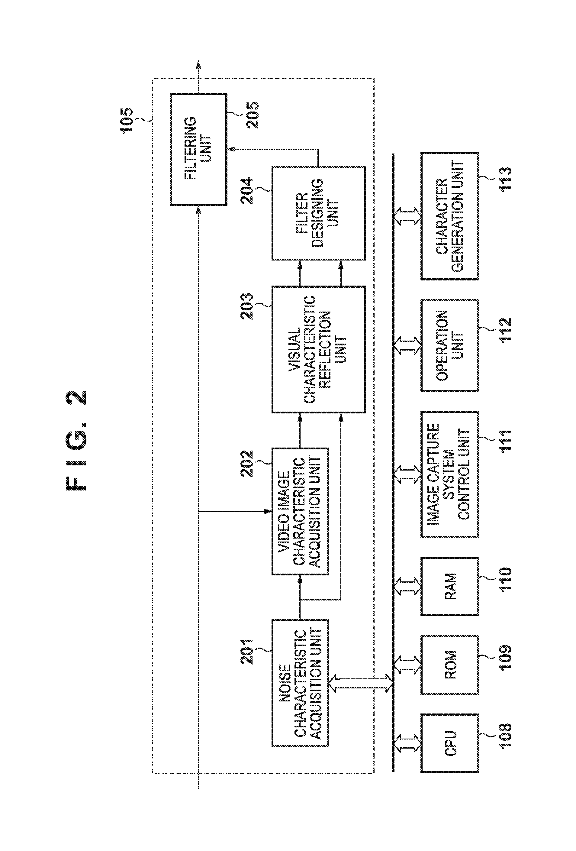
[0026]The present embodiment designs a filter for temporal noise reduction processing based on a temporal characteristic of noise and a temporal frequency response characteristic of vision. Specifically, a temporal characteristic of noise of an image capture device is acquired, and a Wiener filter is designed based on a noise characteristic that is multiplied by a time visual characteristic and an estimation value of a temporal characteristic of an ideal video image that does not have noise. Since the temporal characteristic of noise generally differs in accordance with image capture conditions, it is possible to apply an adaptive filter to noise reduction in accordance with noise and video image characteristics at the time of image capture. Moreover, with the present invention, since the time response characteristic of vision is taken into consideration when a filter is designed, the filter is designed such that a noise reduction effect is increased when a video image is viewed by ...

embodiment 2

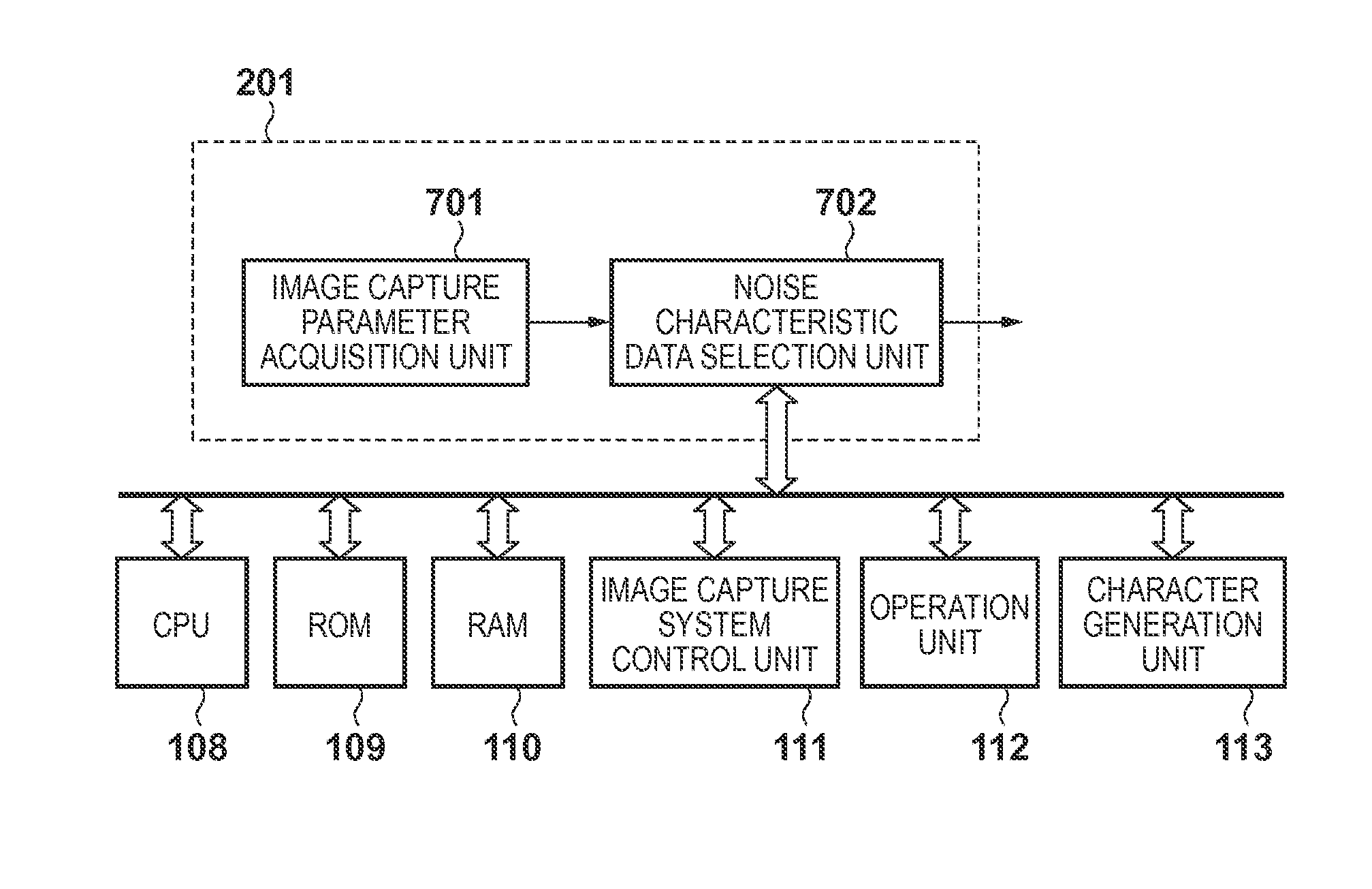
[0068]In Embodiment 1, a method of capturing an image in a state in which a lens cover is closed was used in order to acquire a noise characteristic, and thus, a step for acquiring a noise characteristic for each image capture was required. In contrast, in the present embodiment, a pre-acquired noise characteristic is used when a filter is designed. In the present embodiment, some types of noise characteristics are acquired in advance in accordance with ISO sensitivity that have great effects on a noise characteristic to design a Wiener filter using them. In the present embodiment, it is possible to omit a step for acquiring a noise characteristic for each image capture, and thus, there is an advantage in capturing an image smoothly. A difference from Embodiment 1 will be described below.

[0069]Configuration of Noise Characteristic Acquisition Unit 201

[0070]The operations of the noise characteristic acquisition unit 201 will be described in detail below. FIG. 7 is a schematic diagram...

embodiment 3

[0073]In Embodiment 1, the ideal video image signal S that does not have noise was estimated based on the input video image signal V and the noise characteristic N. Thus, an error of estimating the video image signal S in Embodiment 1 was not prevented from occurring, and there was a case when a sufficient noise reduction effect was not obtained depending on a video image. In view of this, in the present embodiment, the ideal video image signal S that does not have noise is set as a reference video image captured in advance to design a Wiener filter. Here, the reference video image refers to a video image that has little noise. For example, examples of the reference video image includes a video image captured at low sensitivity under bright ambient light, and the like. In the present embodiment, the reference video image is acquired in advance in accordance with a frame rate and a shutter speed that have great effects on characteristics of the video image. A difference from Embodime...


PUM


Abstract

A noise reduction apparatus includes an input unit to input a captured image signal from a capturing unit. An acquisition unit acquires, according to a user operation, a temporal noise signal of the capturing unit based on the captured image signal. An estimation unit estimates an ideal image signal that has no noise, based on the captured image signal and the temporal noise signal. A removing unit removes a temporal frequency component higher than a predetermined threshold from each of the estimated ideal image signal and the acquired temporal noise signal. A generating unit generates a filter used for temporal noise reduction for a captured image signal in accordance with an added signal obtained by adding the ideal image signal from which the temporal frequency component has been removed by the removing unit and the noise signal from which the temporal frequency component has been removed by the removing unit.

Description

CLAIM OF PRIORITY[0001]This application claims the benefit of Japanese Patent Application No. 2012-120138, filed May 25, 2012, which is hereby incorporated by reference herein in its entirety.BACKGROUND OF THE INVENTION[0002]1. Field of the Invention[0003]The present invention relates to noise reduction technology that reduces noise by performing temporal filtering on a video image signal of a moving image captured by a digital video camera, or the like, and to a noise reduction apparatus and a noise reduction method to which the noise reduction technology is applied.[0004]2. Description of the Related Art[0005]Conventionally, various noise reduction methods have been developed in order to improve the image quality of image capture devices. Video noise reduction technology is broadly divided into spatial filter-type noise reduction that performs spatial filtering and temporal filter-type noise reduction that performs temporal filtering.[0006]Temporal filter-type noise reduction has ...

Claims


Application Information

Patent Timeline
Patent Type & Authority Patents(United States)
IPC IPC(8): H04N5/217H04N5/21H04N5/232H04N17/00H04N5/00H04N9/083
CPCH04N5/21H04N5/23229H04N17/002H04N23/80
Inventor IKEDA, SATOSHI
Owner CANON KK
Why Eureka
Eureka Blog
Learn More