Eureka AIR delivers breakthrough ideas for toughest innovation challenges, trusted by R&D personnel around the world.

System and method of imaging for increasing image resolution

Inactive Publication Date: 2016-04-05
PHO IMAGING
View PDF15 Cites 0 Cited by
  • Summary
  • Abstract
  • Description
  • Claims
  • Application Information

AI Technical Summary

Benefits of technology

The present invention provides an imaging system using pixel-to-pixel registration for increasing the resolution of a color image. The system comprises a camera lens for collecting an incoming light beam to thereby output an image-forming light beam. The system further comprises a plurality of beam splitters that split the light beam into multiple beams, and a plurality of color image sensors that individually sense the scene with different focus to yield multiple captured images. A computational unit is included in the system that calculates a geometrical transformation to align the color image sensors by performing translation and rotation on them with respect to the beam splitters. The aligned images are then combined to output a high-resolution image with pixel-to-pixel registration. The system has a high degree of flexibility and can be used for high-speed imaging, high-dynamic range imaging, and selectable focus depths simultaneously. The computational unit can perform image cropping and use raw image data to compute the geometrical transformation. The individual color image sensors can be designed to be rotatable on a plane parallel to the beam splitter and can be fixed with respect to each other. Overall, the invention provides a highly improved imaging system with enhanced resolution and flexibility.

Problems solved by technology

The disadvantage is that the yield of silicon decays sharply, if not exponentially, with its growing size.
Although it is known that an image sensor can increase the number of photodetectors by diminishing the size of each photodetector and its associated integrated circuit, it results in an undesirable electrical cross-talk due to a decreased proximity among different components in a circuit and a low of yield due to a higher density and hence a higher manufacturing cost.
Although this method can improve the color and alias of an output image, the actual detail and contrast are not close to a quality of an image sensor that is quadruple in the original image resolution used in a pixel shifting method.
Also, this pixel shifting method poses impact on the resultant frame rate of a camera due to a repeated movement and exposure time on an image sensor.
Also, this method is not desirable in capturing moving objects.

Method used


Image

  • System and method of imaging for increasing image resolution
  • System and method of imaging for increasing image resolution
  • System and method of imaging for increasing image resolution

Examples


Embodiment Construction

[0030]As used herein, the singular and plural can be used interchangeably regardless of whether the definition refers to the singular or plural term unless otherwise indicated.

[0031]Embodiments of the system disclosed in the present invention are described with specificity and are shown with specific component parameters. It should be noted that the system as disclosed herein is not limited to those parameters ranges or any engineering tolerance.

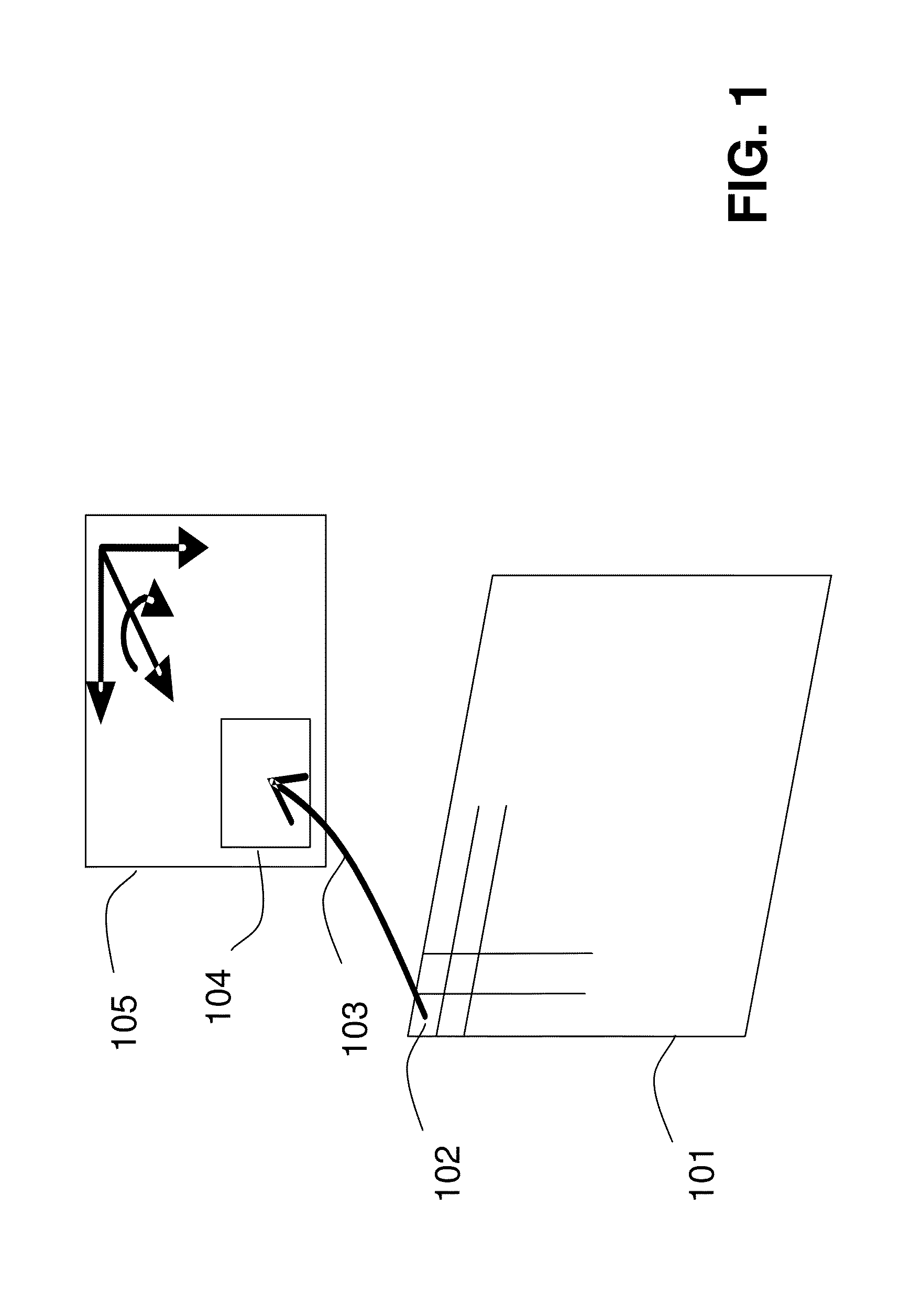
[0032]An aspect of the present invention is to provide an imaging system using pixel-to-pixel registration for increasing the resolution of a color image.

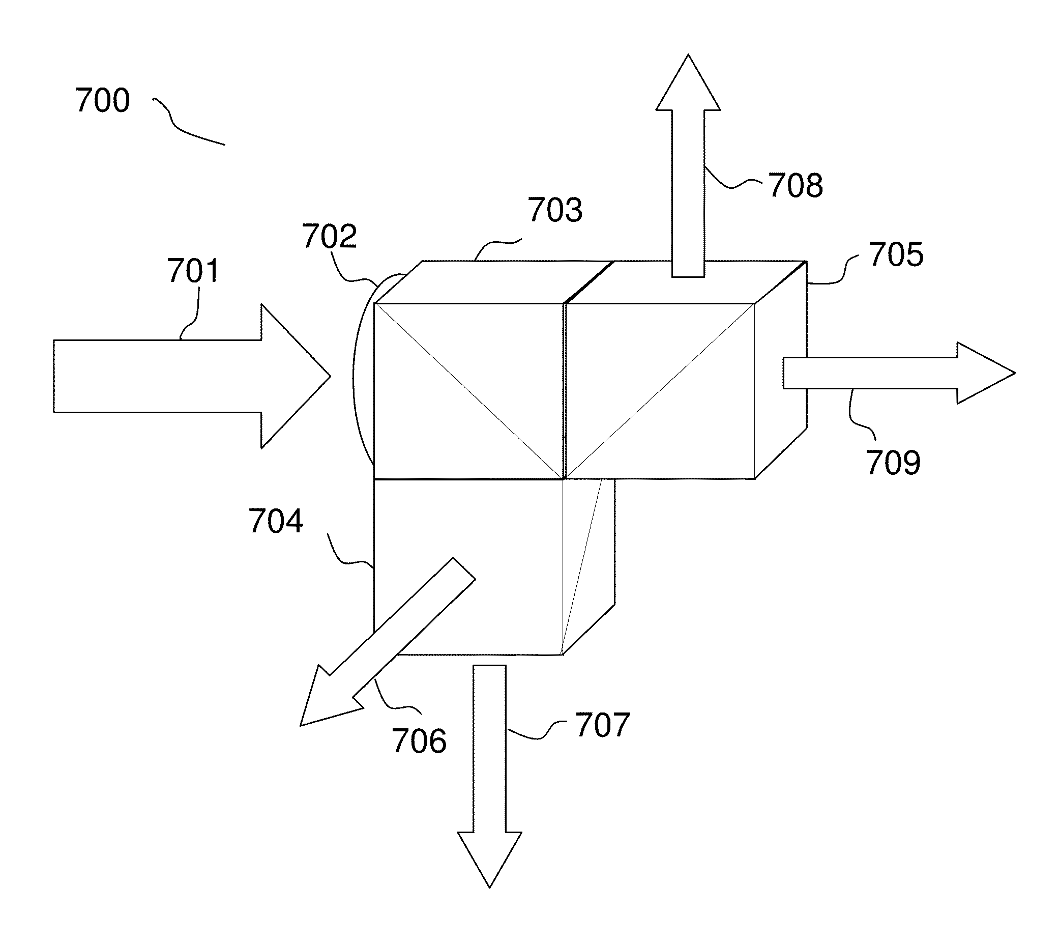
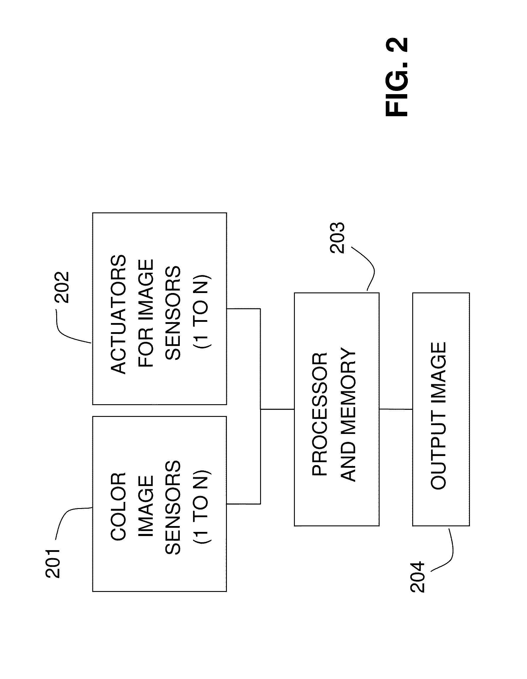
[0033]The system includes a plurality of multiple-DOF (degree of freedom) actuators and beam splitters. A beam splitter is configured to split and direct an incoming light beam into a plurality of paths. Then these split beams may be further split into a plurality of light beams using a plurality of beam splitters. At least two of the light beams after splitting are directed to a plurality ...


PUM


Abstract

An imaging system for increasing image resolution is provided. In one embodiment, the system comprises a camera lens, beam splitters, color image sensors, multiple-DOF (degree of freedom) actuators, and a computational unit. One beam splitter receives light from the camera lens, and each color image sensor receives a split light beam from one of the beam splitters. The color image sensors are configured to individually sense a scene with different focus to yield captured images. Each actuator connects to an individual color image sensor for translating and rotating the individual color image sensor. The computational unit is configured to: compute a geometric transformation among the captured images so as to configure the actuators to align the color image sensors by performing translation and rotation on the color image sensors; and to perform luminance unification on the captured images to output a resultant image.

Description

FIELD OF THE INVENTION[0001]The present invention generally relates to an imaging system that uses a plurality of color image sensors and a plurality of multiple-degree-of-freedom actuators for increasing a color image's resolution. In particular, the present invention relates to such imaging system that further employs beam splitting and image registration for realizing an increase of the image resolution.BACKGROUND[0002]Techniques to increase the resolution of a color image by an imaging system are classified into four types.[0003]The first type involves the development of a solid state charge coupled device (CCD) or a CMOS image sensor or a solid state photosensitive sensor with a color filter array (CFA) which consists of more photodetectors, also known as an active-pixel sensor on its plane of photosensitive pixel arrays. The more photodetectors on the plane of an image sensor, the higher image resolution one can read from such an image sensor. To increase the image resolution ...

Claims


Application Information

Patent Timeline
IPC IPC(8): H04N5/225
CPCH04N5/2258H04N5/2254H04N23/45H04N25/48H04N25/134
Inventor LAU, TAK KITLIN, KAI WUN
Owner PHO IMAGING
Why Eureka
Eureka Blog
Learn More