Methods and systems for boost control

a boost control and boost technology, applied in the direction of charge feed system, combustion engine, non-fuel substance addition to fuel, etc., can solve the problems of increasing the risk of condensation at both the compressor inlet and the charge air cooler outlet, increasing the risk of water entering the engine, damage to the blades, etc., to improve fuel economy, improve peak power output, and increase engine dilution

Active Publication Date: 2016-04-12
FORD GLOBAL TECH LLC
View PDF40 Cites 30 Cited by
  • Summary
  • Abstract
  • Description
  • Claims
  • Application Information

AI Technical Summary

Benefits of technology

[0002]Engine systems may be configured with a boosting device, such as a turbocharger, for providing a boosted aircharge and improving peak power outputs. Therein a turbine is rotated using energy from an exhaust flow, the turbine then driving a compressor which delivers a boosted aircharge to the engine intake. In an effort to meet stringent federal government fuel economy standards, engine systems may also be configured with exhaust gas recirculation (EGR) systems wherein at least a portion of the exhaust gas is recirculated to the engine intake. For example, the EGR system may be a low-pressure EGR system (LP-EGR) that recirculates exhaust gas from downstream of an exhaust turbine to upstream of an intake compressor. EGR benefits include an increase in engine dilution and improvements in fuel economy.
[0003]However, since EGR has a relatively large water content, the addition of LP-EGR to the intake at a pre-compressor location increases the risk of condensation at both a compressor inlet as well as a charge air cooler outlet. Specifically, under cold ambient conditions, when the humid EGR is mixed with cold ambient air, water droplets can form. Water droplets impacting the compressor blades which are rotating at high speeds (e.g., 200,000 rpm or above) can cause damage to the blades. In addition, since the ingested water slows the rate of combustion, the introduction of water into the engine can increase the likelihood of misfire events.
[0004]To address these issues, engine control systems may employ various approaches to limit the condensation. One example approach is shown by Joergl et al. in US publication 2009 / 0071150. Therein, a mixing pipe is located inside an intake tube for receiving EGR. To reduce damage to the compressor wheel, fresh air is mixed with EGR inside the mixing pipe before the mixture is delivered onto the compressor wheel in an area of low circumferential speed. Another example approach is shown by Clarke et al in U.S. Pat. No. 8,286,616. Therein, an amount of exhaust recirculated via an LP-EGR system and an EGR passage coupled between the exhaust manifold and the intake manifold is adjusted responsive to the humidity in the combustion chamber so as bring the estimated humidity to a desired range.
[0006]In one example, some of the above issues may be addressed by a method for a boosted engine comprising adjusting a relative amount of compressed air recirculated to upstream of a compressor from a first passage downstream of the compressor and downstream of an intercooler, and from a second passage downstream of the compressor and upstream of the intercooler based on compressor inlet temperature. The adjusting may be further based on EGR. In this way, a temperature and humidity controlled mixture of compressor recirculation flow and EGR can be delivered to the engine to provide engine dilution while reducing the risk of condensation.
[0009]In this way, by recirculating warmer boosted air from upstream of a charge air cooler to a compressor inlet when condensation is possible, a temperature-controlled mixture may be provided at the compressor inlet using existing engine hardware. By warming the compressor inlet using the compressor recirculation flow, condensation at the compressor inlet is reduced even as ambient conditions or EGR conditions fluctuate. By reducing the amount of EGR condensation ingested at a compressor, condensation related combustion issues may be reduced. For example, misfires may be reduced. In addition, degradation of compressor components due to impingement of condensate on the compressor blades at high rotation speeds is reduced. Overall, the performance and life of the compressor is improved.

Problems solved by technology

However, since EGR has a relatively large water content, the addition of LP-EGR to the intake at a pre-compressor location increases the risk of condensation at both a compressor inlet as well as a charge air cooler outlet.
Water droplets impacting the compressor blades which are rotating at high speeds (e.g., 200,000 rpm or above) can cause damage to the blades.
In addition, since the ingested water slows the rate of combustion, the introduction of water into the engine can increase the likelihood of misfire events.
However, the inventors herein have identified issues with such approaches.
For example, the approach of '150 requires an additional mixing pipe which can add component cost and complexity.
As a result, even with the above mentioned mixing approaches, condensation can occur, leading to compressor degradation.

Method used


Image

  • Methods and systems for boost control
  • Methods and systems for boost control
  • Methods and systems for boost control

Examples


embodiment 200

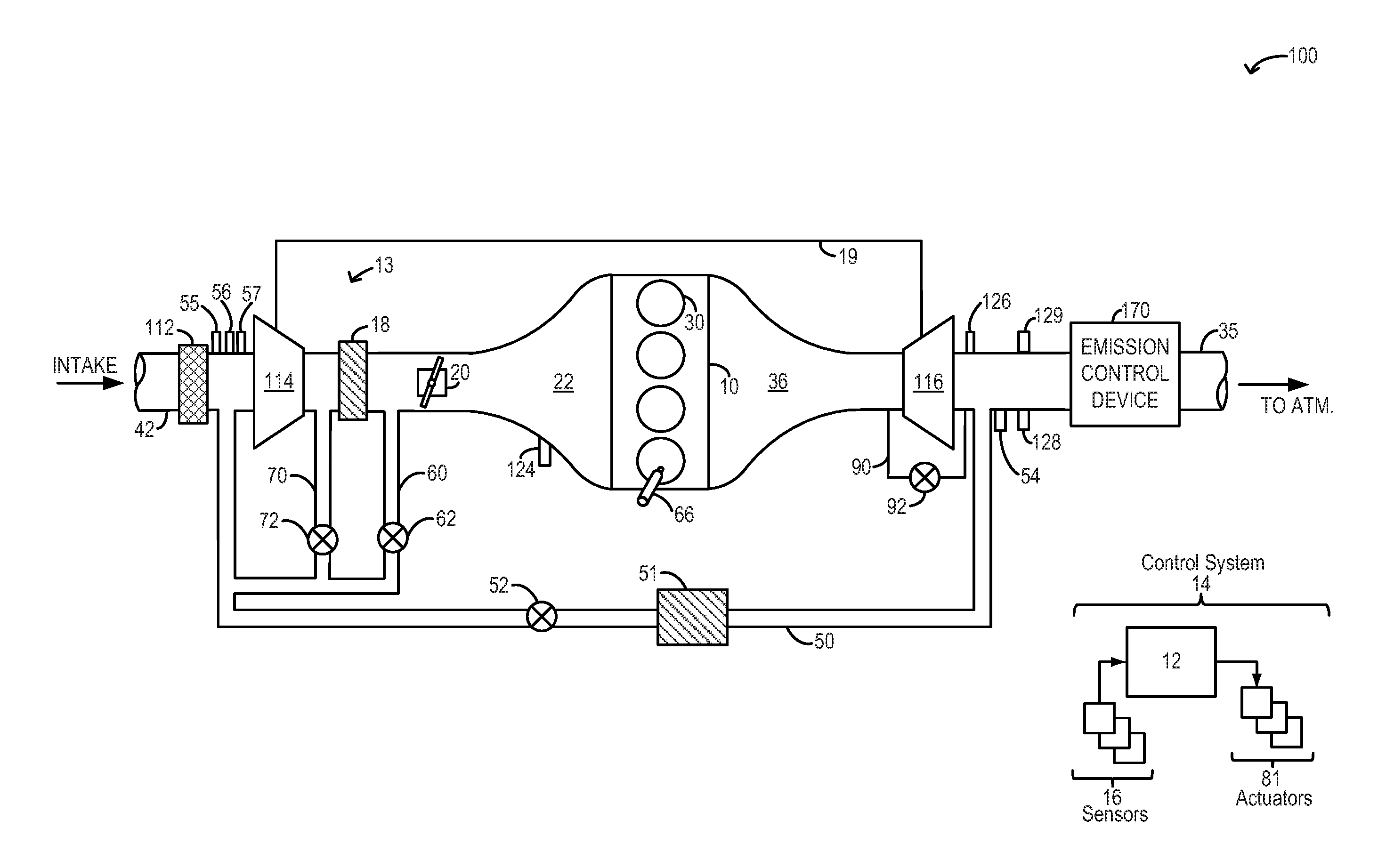
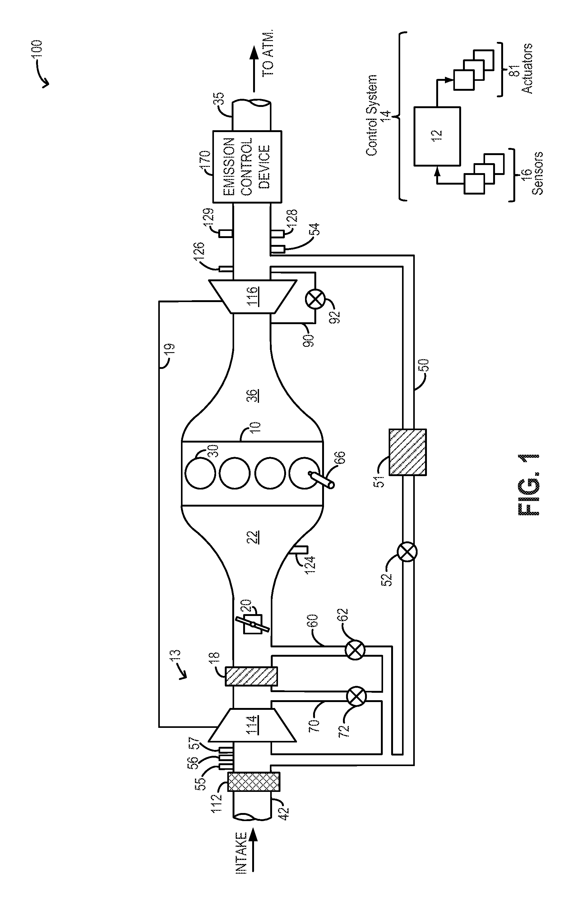
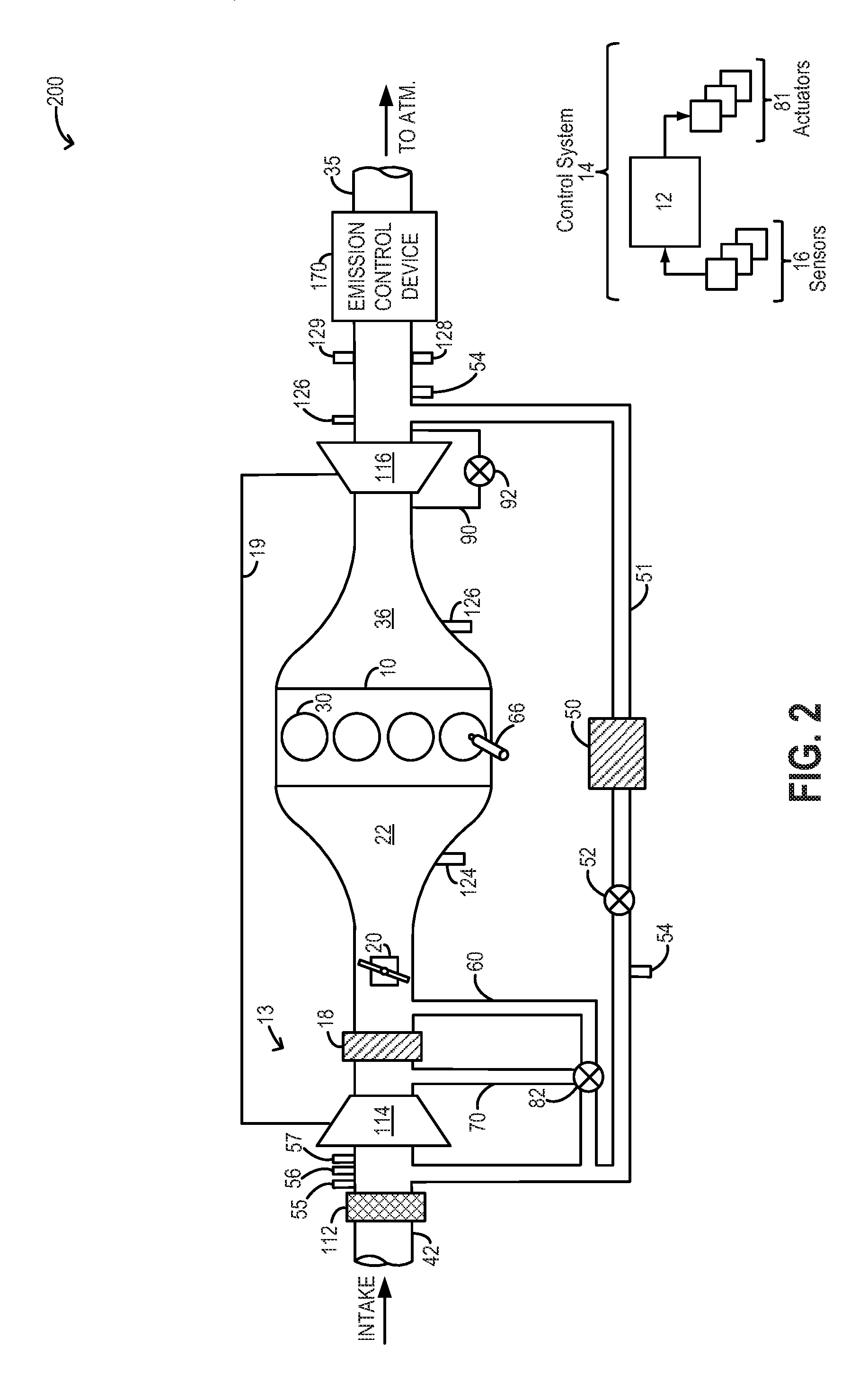
[0023]One or more valves may be coupled to the recirculation passages to control an amount of flow recirculated to the compressor inlet. In one example embodiment, depicted at FIG. 1, the first passage may include a first valve 62 for adjusting an amount of cooler recirculation flow recirculated to the compressor inlet while the second passage may include a second valve 72 for adjusting an amount of warmer recirculation flow recirculated to the compressor inlet. In an alternate embodiment 200, as depicted at FIG. 2, flow through the first and second passages may be controlled by a common valve 82. Common valve 82 may be an on-off type single variable valve for controlling flow along the first and second passages. Alternatively, common valve 82 may be a thermostat-controlled proportioning valve that is configured to adjust an amount of flow received at the compressor inlet from the first and second passages to provide a temperature-controlled recirculation flow mixture at the compres...

embodiment 800

[0037]It will be appreciated that while the embodiments of FIGS. 1-2 show two distinct compressor recirculation flow passages, in still other embodiments, only one flow passage may be provided. For example, as shown in embodiment 800 of FIG. 8, the engine system may be configured with a single compressor recirculation passage 60 including compressor recirculation valve 62 for recirculating cooled compressed air from downstream of charge air cooler 18 to the inlet of compressor 114. Therein, in response to an indication of surge, the controller may open (e.g., fully open) valve 62 to recirculate compressed air from downstream of the charge air cooler and upstream of the intake throttle to the compressor inlet. By addressing surge with only cooled compressed air, that is compressed aircharge that has been cooled upon passing through the charge air cooler, a temperature amplification effect of recirculation flow is reduced. In addition, by locating the compressor bypass system post the...


PUM


Abstract

Methods and systems are provided for varying a proportion of compressed air recirculated to a compressor inlet from a location downstream of the compressor and upstream of a charge air cooler and a location downstream of the charge air cooler. A temperature-controlled compressor recirculation flow is used to reduce condensation from EGR being ingested into the compressor. The temperature-controlled compressor recirculation flow is also used to address compressor surge.

Description

FIELD[0001]The present application relates to methods and systems for using compressor recirculation flow to improve boost control.BACKGROUND AND SUMMARY[0002]Engine systems may be configured with a boosting device, such as a turbocharger, for providing a boosted aircharge and improving peak power outputs. Therein a turbine is rotated using energy from an exhaust flow, the turbine then driving a compressor which delivers a boosted aircharge to the engine intake. In an effort to meet stringent federal government fuel economy standards, engine systems may also be configured with exhaust gas recirculation (EGR) systems wherein at least a portion of the exhaust gas is recirculated to the engine intake. For example, the EGR system may be a low-pressure EGR system (LP-EGR) that recirculates exhaust gas from downstream of an exhaust turbine to upstream of an intake compressor. EGR benefits include an increase in engine dilution and improvements in fuel economy.[0003]However, since EGR has ...

Claims


Application Information

Patent Timeline
Patent Type & Authority Patents(United States)
IPC IPC(8): F02B33/44F02M25/07F02B29/04F02B37/16
CPCF02M25/07F02B29/04F02B29/0493F02B37/16F02M25/0709F02M26/06F02M26/00Y02T10/12
Inventor ULREY, JOSEPH NORMANBUCKLAND, JULIA HELENMCCONVILLE, GREGORY PATRICK
Owner FORD GLOBAL TECH LLC
Why Eureka
Try Eureka