
Cap nail

Active Publication Date: 2016-04-12
K & R IND
View PDF67 Cites 4 Cited by
  • Summary
  • Abstract
  • Description
  • Claims
  • Application Information

AI Technical Summary

Benefits of technology

This patent describes a roofing fastener that can securely attach a waterproof membrane to a roof deck without creating any leaks. The fastener consists of a resilient flat disk and a few nails with a flat head and a pointy end. The nails are fixedly embedded in the disk, and there are openings in the disk to allow adhesive to pass through. The fastener is made of a strong plastic material. The patent also describes a flexible disk that can flex and create a wedge effect on the roof deck, making it more secure than the standard cap nail. Overall, this roofing fastener is designed to improve the effectiveness and quality of roofing systems.

Problems solved by technology

First, the roofing materials prevent moisture from reaching an underlying support member such as concrete or plywood.
This wind or low pressure can rip the asphalt / base ply sheet roofing materials off the underlying roofing substrate if not sufficiently anchored.
Often, they have limited capacity to secure the base sheet, because they will only provide 50-100 pounds of resistance.
Tear out strength test results conducted on these roofing fasteners installed in plywood vary greatly from fastener to fastener due to inconsistency of plywood.
Moreover, due to increasing losses in the insurance industry, pull out requirements for fasteners have been revised upward.
Often these cap nails fail to meet the new and higher industry standards.
Problems exist with other fasteners as well.
This multiple piece construction increases the cost of making the fastener and complexity of installation.
Further, even these multiple component fasteners also have difficulty in meeting today's desire for providing higher load values without pulling out or tearing the roofing material.

Method used


Image

  • Cap nail
  • Cap nail
  • Cap nail

Examples


Embodiment Construction

[0023]As required, detailed embodiments of the present invention are disclosed herein; however, it is to be understood that the disclosed embodiments are merely exemplary of the invention that may be embodied in various and alternative forms. The figures are not necessarily to scale; some features may be exaggerated or minimized to show details of particular components. Therefore, specific structural and functional details disclosed herein are not to be interpreted as limiting, but merely as a representative basis for teaching one skilled in the art to variously employ the present invention.

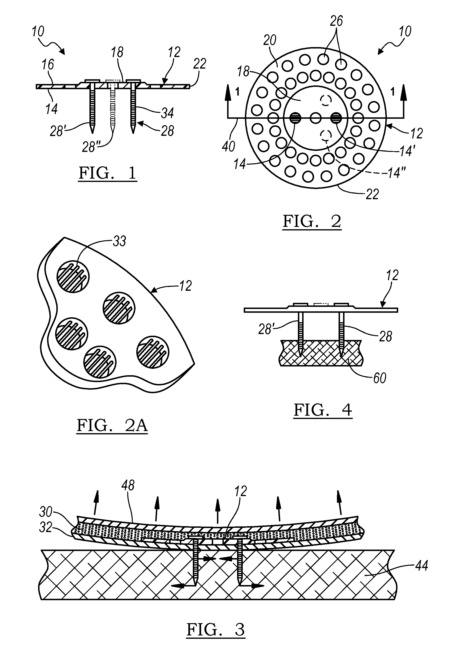
[0024]FIG. 1 shows a side, sectional view of a first roofing fastener embodiment 10, taken along the section line 1-1 of FIG. 2. The roofing fastener 10 comprises a disk 12 having a flat lower surface 14 and has a generally flat upper surface 16. Disk 12 has a relatively thick central region 18 surrounded by an annular region 20 which preferably tapers downwardly from the central region 18 toward...


PUM


Abstract

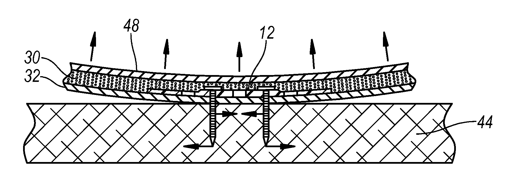
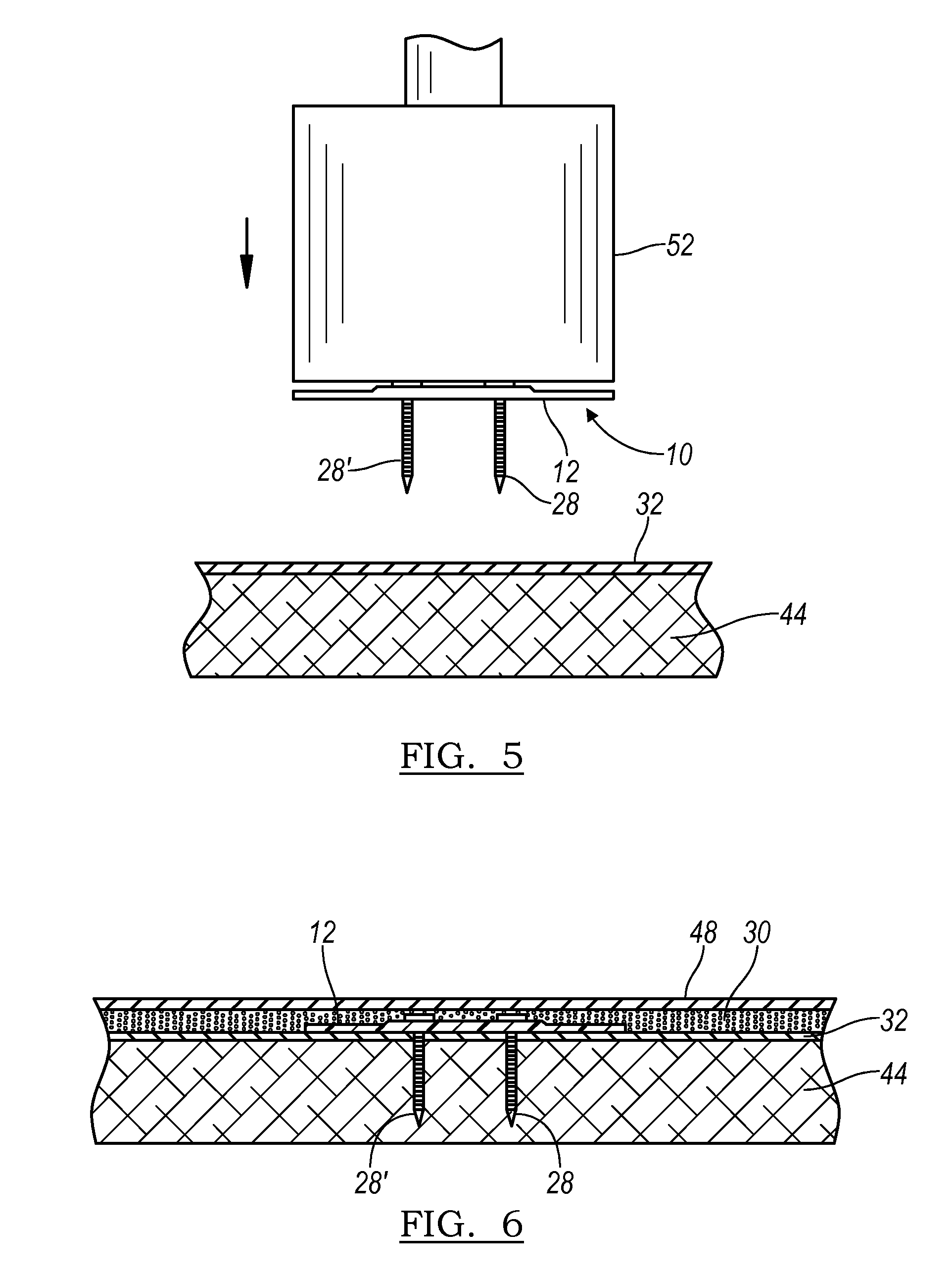
A flexible roofing fastener is provided for securing water resistant material to a substrate such as wood and preventing leaks through holes created in the material by the roofing fastener. The roofing fastener includes a resilient disk having a flat lower surface, a thick central region and an annular region having a thickness that tapers downwardly from a central area toward a periphery. The disk central region has a plurality of evenly spaced apart flat-headed nails extending downwardly there through. The annular region having plurality of holes through which sealing material can flow. A flexible disk, when upload flexes in a cup shape causing wedge effect on the anchoring points in the substrate, allowing this fastener to perform better when under a simulated wind uplift testing of various modified bitumen Roof Systems.

Description

CROSS-REFERENCE TO RELATED APPLICATIONS[0001]This application is a continuation of U.S. application Ser. No. 13 / 355,899 filed Jan. 23, 2012, the disclosure of which is hereby incorporated in its entirety by reference herein.BACKGROUND OF THE INVENTION[0002]1. Field of the Invention[0003]The present invention relates generally to a roofing fastener having a disk that distributes pressure over greater areas than do heads of nails alone when used to secure sheets of water-resistant materials to substrates such as wood and more specifically to roofing fasteners having resilient disks configured to moderate pressures along their peripheral edges to prevent damage to the material being supported by the roofing fasteners while preventing leaks through holes created in the material by the roofing fasteners.[0004]2. Background Art[0005]Roofing components are applied to the top of roofs for several reasons. First, the roofing materials prevent moisture from reaching an underlying support memb...

Claims


Application Information

Patent Timeline
IPC IPC(8): E04B5/00F16B15/00E04D5/14E04D3/36E04B1/76
CPCF16B15/00E04D5/146E04D3/3603E04B1/7633E04D3/3606E04D5/145E04D5/143E04D5/147E04D5/148
Inventor POWELL, KENNETH S.
Owner K & R IND
Learn More