Device For Gripping Substrate Without Contact

Active Publication Date: 2015-11-12
ZS HANDLING +1
View PDF3 Cites 3 Cited by
  • Summary
  • Abstract
  • Description
  • Claims
  • Application Information

AI Technical Summary

Benefits of technology

[0018]According to embodiments of the invention, it is po

Problems solved by technology

However, when the vacuum chuck is used, the operation of holding the glass substrates under the vacuum causes minute scratches having the size of 3 μm or less to form on the surface of glass substrates, thereby deteriorating the quality of glass substrates.
In addition, the application of the method of gripping glass substrates using compressed air without making contact therewith has the following problem.
Whe

Method used


Image

  • Device For Gripping Substrate Without Contact
  • Device For Gripping Substrate Without Contact
  • Device For Gripping Substrate Without Contact

Examples


Example

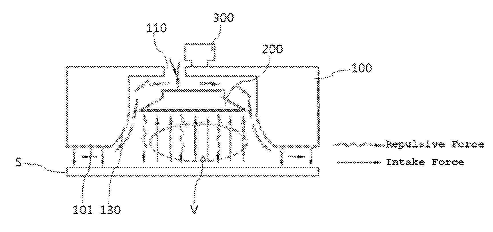
[0024]Reference will now be made in detail to a device for gripping a substrate without contact according to the present invention, various embodiments of which are illustrated in the accompanying drawings and described below, so that a person having ordinary skill in the art to which the present invention relates can easily put the present invention into practice.

[0025]Throughout this document, reference should be made to the drawings, in which the same reference numerals and signs are used throughout the different drawings to designate the same or similar components. In the following description of the present invention, detailed descriptions of known functions and components incorporated herein will be omitted when they may make the subject matter of the present invention unclear.

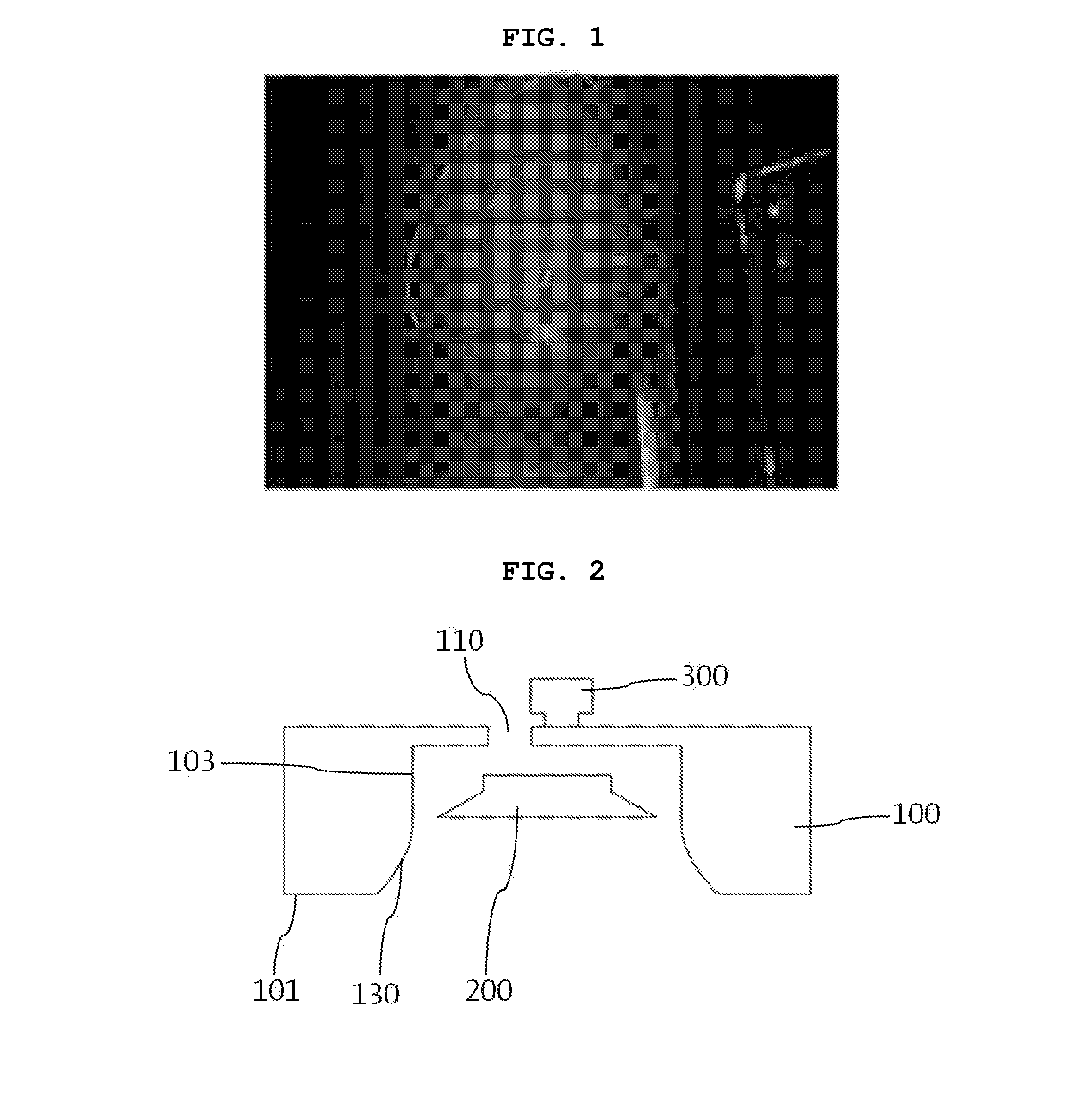
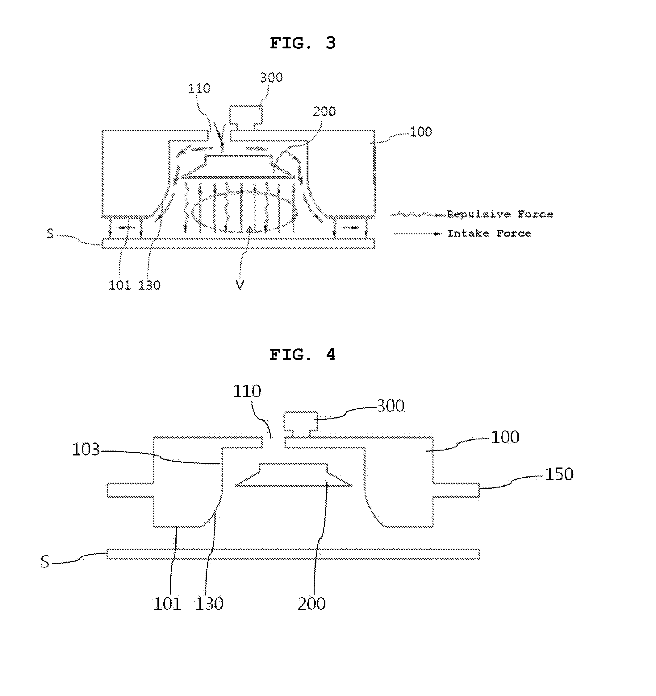
[0026]FIG. 2 is a schematic cross-sectional view showing a device for gripping a substrate without contact according to an embodiment of the invention, and FIG. 3 is a cross-sectional view illustrating a...


PUM


Abstract

A device for gripping a substrate without contact with which the substrate can be more securely transported. In the device, a housing cap has an air inlet in the upper surface and a lower opening, the lower opening communicating with the air inlet such that air introduced through the air inlet exits through the lower opening. A contour of the lower opening in its vertical cross section is convexly rounded such that the introduced air is guided along a horizontal undersurface of the housing cap. A nozzle is disposed in an inner hollow space of the housing cap, and has an inclined surface such that the width of the nozzle gradually decreases in the direction from the undersurface of the nozzle to the upper surface of the nozzle adjacent to the air inlet. The undersurface of the nozzle is at a predetermined distance from the inner surface of the housing cap. An ultrasonic shaker applies ultrasonic vibration to the housing cap.

Description

BACKGROUND OF THE INVENTION[0001]1. Field of the Invention[0002]The present invention relates to a device for gripping a substrate without contact, and more particularly, to a device for gripping a substrate without making contact with the substrate.[0003]2. Description of Related Art[0004]Glass substrates used for the fabrication of flat panel displays, such as thin film transistor liquid crystal displays (TFT-LCDs), plasma display panels (PDPs) or electroluminescent (EL) devices, are manufactured through the process of converting molten glass that is produced from a glass melting furnace into a flat plate and the process of cutting the flat plate of glass to a preset size before being transported to a machining line where they are machined. In the machining line, glass substrates are cut again to the dimensions of flat panel displays, and four edges of glass substrates are chamfered. Here, the term “chamfering” refers to grinding the edge surfaces that are sharp and have minute cr...

Claims


Application Information

Patent Timeline
IPC IPC(8): B25B11/00B23Q3/08B24B41/06
CPCB25B11/005B23Q3/088B24B41/06B24B41/005B25J15/06B65G47/91B65G47/911H01L21/67051H01L21/67126H01L21/6838
Inventor KIM, CHAN-KYUZITZMANN, ADOLFKIM, KINAMZIMMERMANN, JOSEFSCHILP, MICHAEL
Owner ZS HANDLING
Why Eureka
Try Eureka