Plug connector, receptacle connector and electrical connector assembly

a technology of receptacle connectors and plug connectors, which is applied in the direction of coupling devices, coupling bases/cases, and coupling devices with two parts, etc., can solve the problems of low-type hybrid electric connectors that cannot be suitable for electrical devices, power modules with large widths, and other electrical connectors that cannot be further mounted on the edge of circuit boards. to achieve the effect of saving the edge space of the circuit board

Active Publication Date: 2016-04-12
OUPIN ELECTRONICS KUNSHAN
View PDF6 Cites 6 Cited by
  • Summary
  • Abstract
  • Description
  • Claims
  • Application Information

AI Technical Summary

Benefits of technology

[0008]Further object of the present invention is to provide an electrical connector assembly including a plug connector and a receptacle connector, which can be stably connected for ensuring the power and signal transmission performance of the both.
[0020]In comparison with the prior art, the plug connector, the receptacle connector and the electrical connector assembly according to the present invention can construct a compact structure by stacking the signal ports and the power ports, thereby saving the edge space of a circuit board and being capable of disposing more other type connectors on the edge of the circuit board. Moreover, the plug power contacts and the receptacle power contacts are respectively mounted in the plug housing and the receptacle power housing according to a special arrangement.

Problems solved by technology

Because the edge space of the circuit board is limited, other electrical connectors can not be further mounted on the edge of the circuit board.
Further, the power module has a large width size.
So, the low type hybrid electric connector can only be suitable for an electrical device, which need a small height, and unsuitable for an electrical equipment, which need add other components onto the edge of the circuit board.

Method used


Image

  • Plug connector, receptacle connector and electrical connector assembly
  • Plug connector, receptacle connector and electrical connector assembly
  • Plug connector, receptacle connector and electrical connector assembly

Examples


Embodiment Construction

[0030]The following description of every embodiment with reference to the accompanying drawings is used to exemplify a specific embodiment, which may be carried out in the present invention. Directional terms mentioned in the present invention, such as “top”, “bottom”, “front”, “back”, “left”, “right”, “top”, “bottom” etc., are only used with reference to the orientation of the accompanying drawings. Therefore, the used directional terms are intended to illustrate, but not to limit, the present invention.

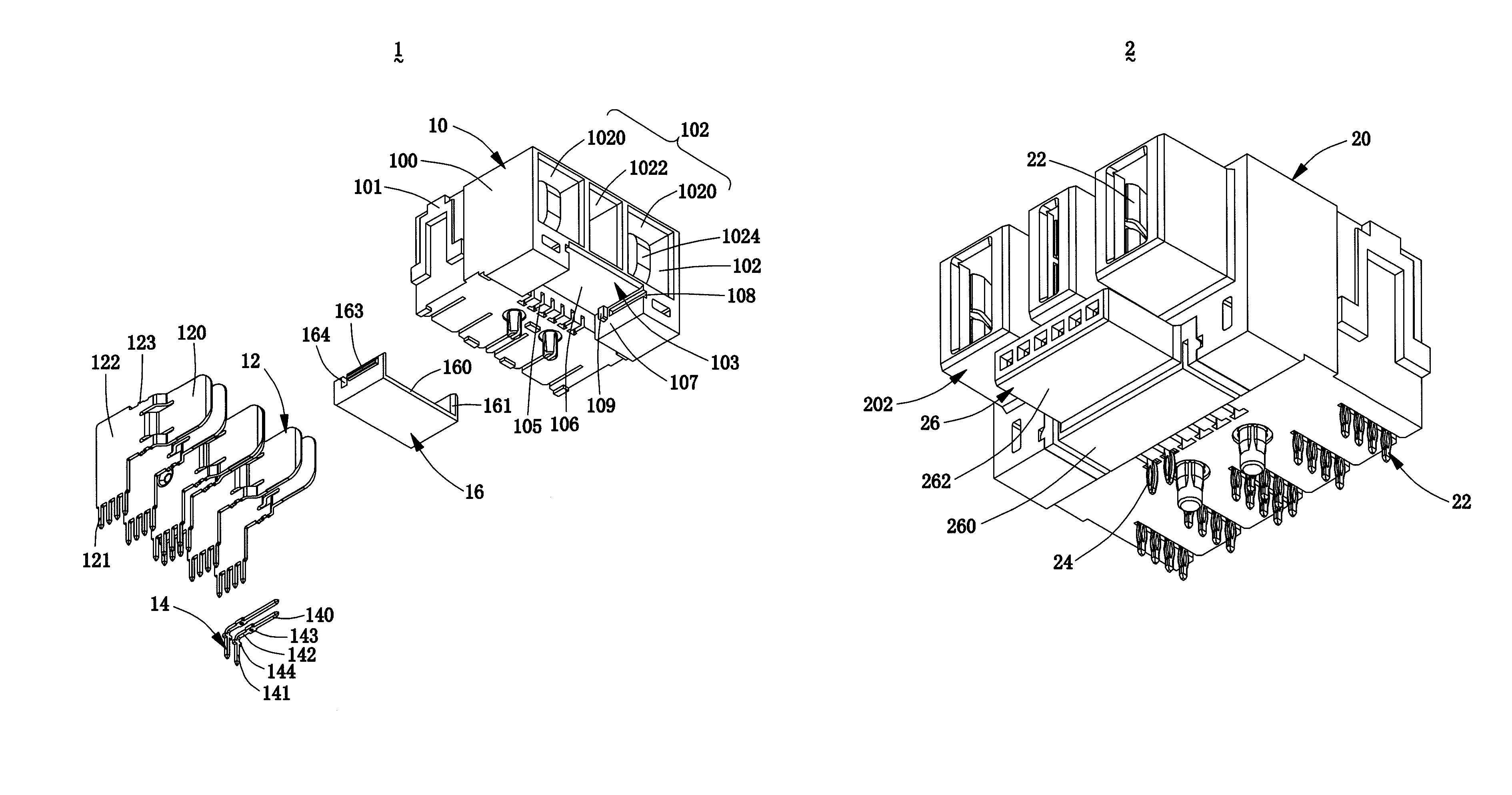
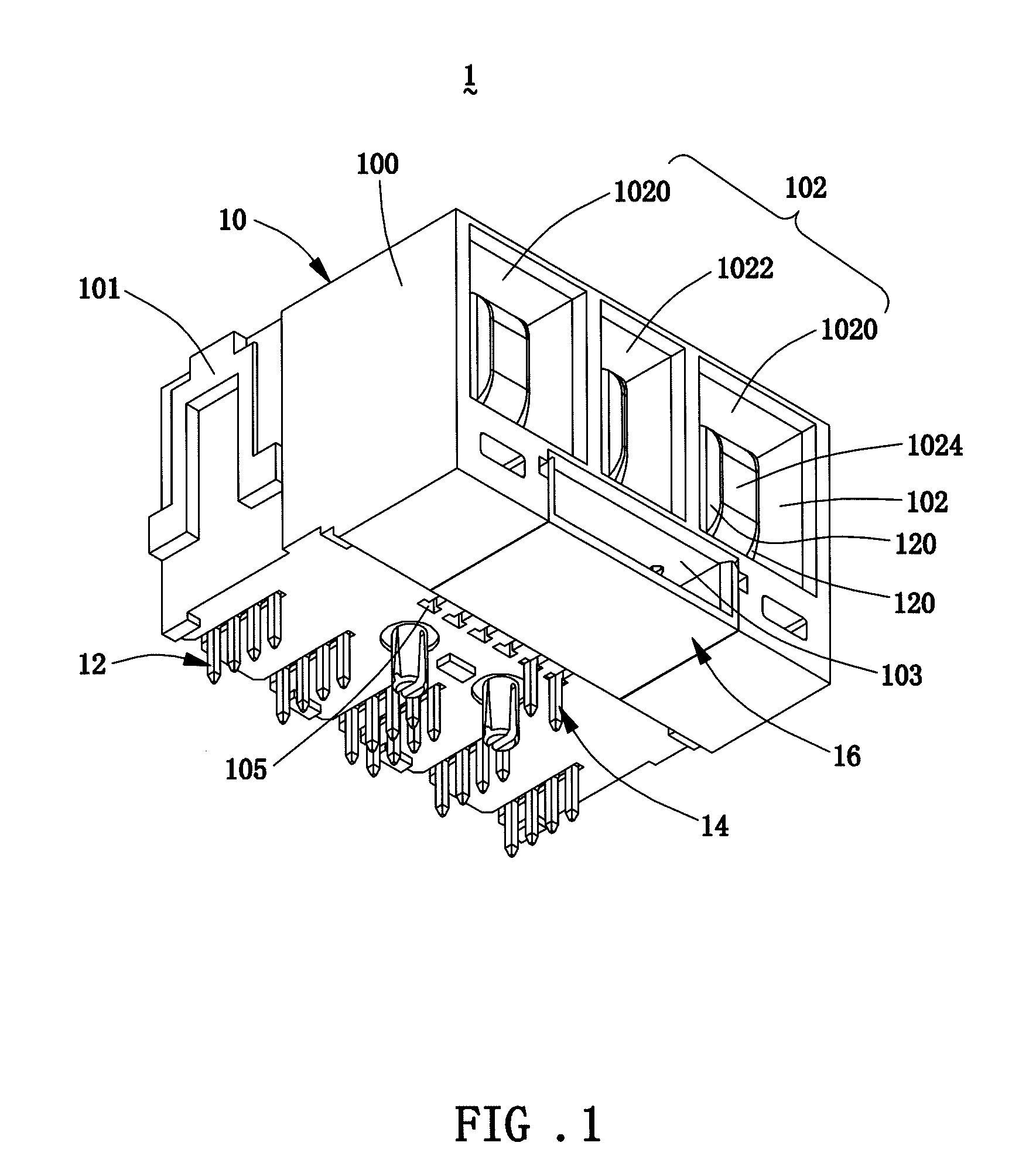
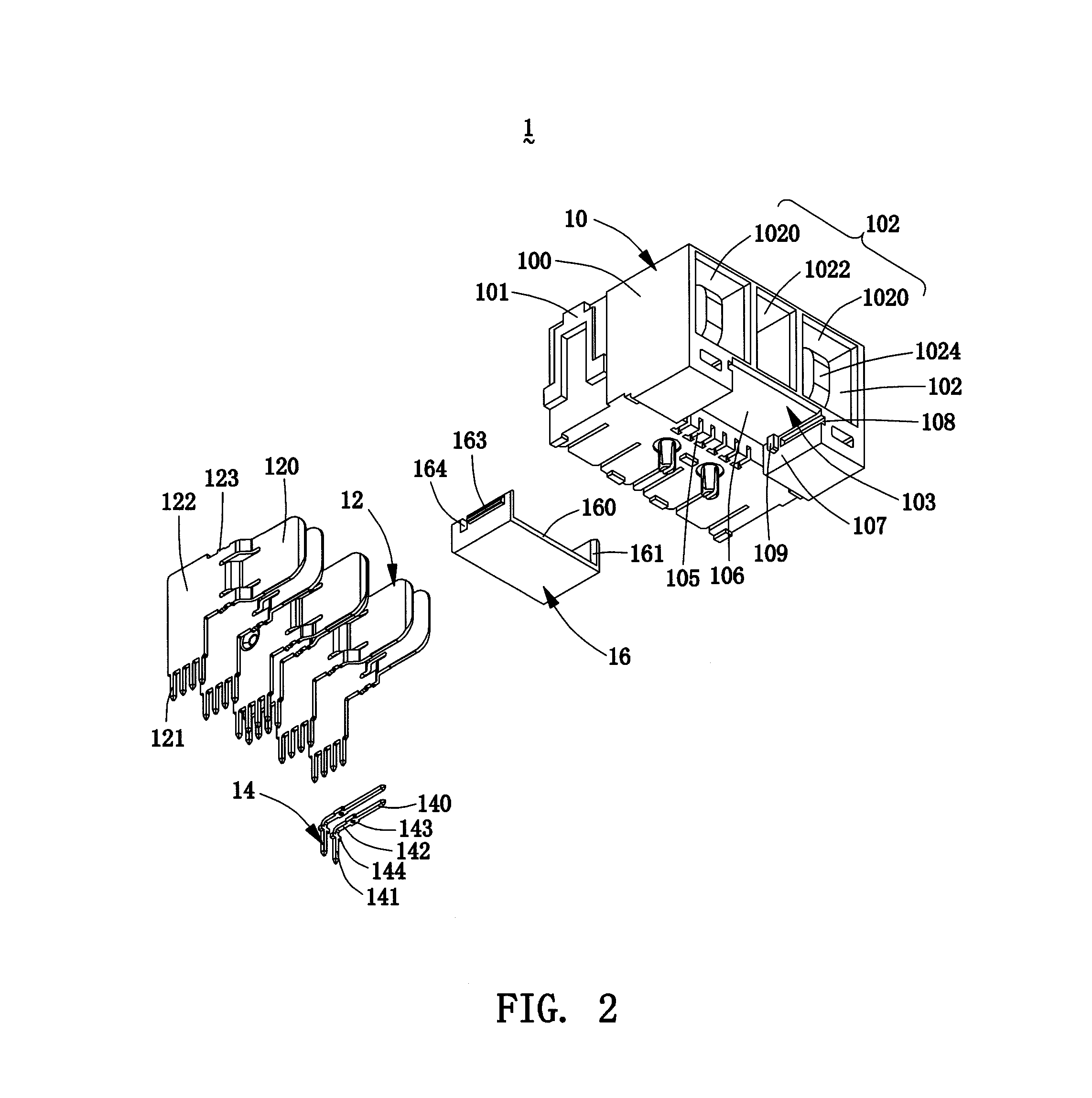
[0031]Please refer to FIGS. 1 to 4, FIG. 1 is a perspective schematic view of a plug connector 1 of the present invention, FIG. 2 is an exploded view of the plug connector 1 shown in FIG. 1, FIG. 3 is a perspective schematic view of the plug connector 1 of the present invention along another direction, and FIG. 4 is an exploded view of the plug connector 1 shown in FIG. 3.

[0032]Please refer to FIGS. 1 to 4, the plug connector 1 of the present invention is a horizontal connector, the...


PUM


Abstract

A plug connector, a receptacle connector and an electrical connector assembly are disclosed. When the plug connector is engaged with the receptacle connector, the power mating bodies and the signal mating body of the receptacle connector respectively enter into the corresponding plug power ports and the plug signal port of the plug connector, and the plug power contacts and the plug signal contacts respectively enter into the receptacle power ports and the receptacle signal ports. The vertical blade-shaped mating end of the plug power contact is inserted between the elastic pieces of the corresponding two receptacle power contacts, and the head of the plug signal contact is inserted into the forked head of the corresponding receptacle signal contact.

Description

BACKGROUND OF THE INVENTION[0001]1. Field of the Invention[0002]The present invention relates to a connector technology, and more particularly to a horizontal plug connector, a horizontal receptacle connector and an assembly of the plug connector and the receptacle connector.[0003]2. Description of the Prior Art[0004]At present, the power function and the signal function are constructed in an electrical connector, but this electrical connector is usually low and hybrid. This electrical connector occupies the small height space, but occupies too much edge space of a circuit board along a length direction thereof. Because the edge space of the circuit board is limited, other electrical connectors can not be further mounted on the edge of the circuit board. For example, U.S. Pat. No. 6,319,075 discloses an electrical connector, in which a power module and a signal module are arranged side by side. Further, the power module has a large width size. So, the low type hybrid electric connec...

Claims


Application Information

Patent Timeline
Patent Type & Authority Patents(United States)
IPC IPC(8): H01R12/00H01R13/46H01R24/60H01R24/68H01R107/00
CPCH01R24/68H01R24/60H01R13/46H01R2107/00H01R12/724H01R27/02
Inventor CHEN, HSIN CHIH
Owner OUPIN ELECTRONICS KUNSHAN
Why Eureka
Try Eureka