Electronic device

a technology of electronic devices and electronic components, applied in the direction of lighting and heating apparatus, electrical apparatus casings/cabinets/drawers, instruments, etc., can solve problems such as unstable working state of electronic devices, and achieve the effect of improving the heat dissipation efficiency of electronic devices

Active Publication Date: 2016-04-12
ASUSTEK COMPUTER INC
View PDF11 Cites 578 Cited by
  • Summary
  • Abstract
  • Description
  • Claims
  • Application Information

AI Technical Summary

Benefits of technology

[0007]An electronic device with a heat conducting pillar is provided to enhance the heat dissipation efficiency.
[0009]The heat conducting pillar may be a solid structure or a hollow structure. When the heat conducting pillar is a hollow structure, the heat conducting pillar includes a sidewall and a passage formed by the surrounded sidewall. The heat conducting pillar may also include a plurality of holes in the sidewall. The upper cover includes a plurality of ventilation holes, and the passage leads to the cooling hole. The electronic device further includes a fan disposed in the accommodating space, the air outside the electronic device is guided into the electronic device through the passage by the fan, and then the air is exhausted through the holes and flows along the path provided by the fan. In this disclosure, the heat conducting pillar connecting the upper cover and the lower cover balances the temperatures of the upper cover and the lower cover to enhance the heat dissipation efficiency of the electronic device.

Problems solved by technology

While the heat generated by the processor cannot be dissipate, the electronic device may work in unstable state.

Method used


Image

  • Electronic device
  • Electronic device
  • Electronic device

Examples


Embodiment Construction

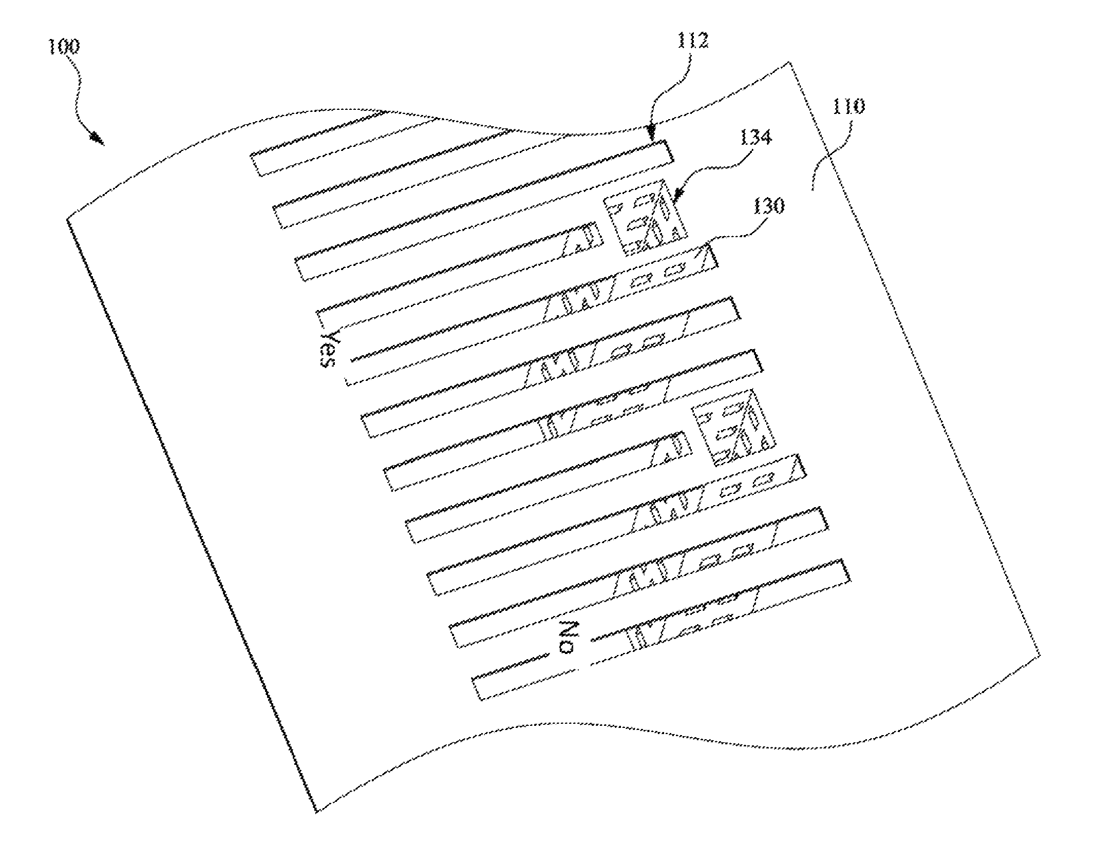
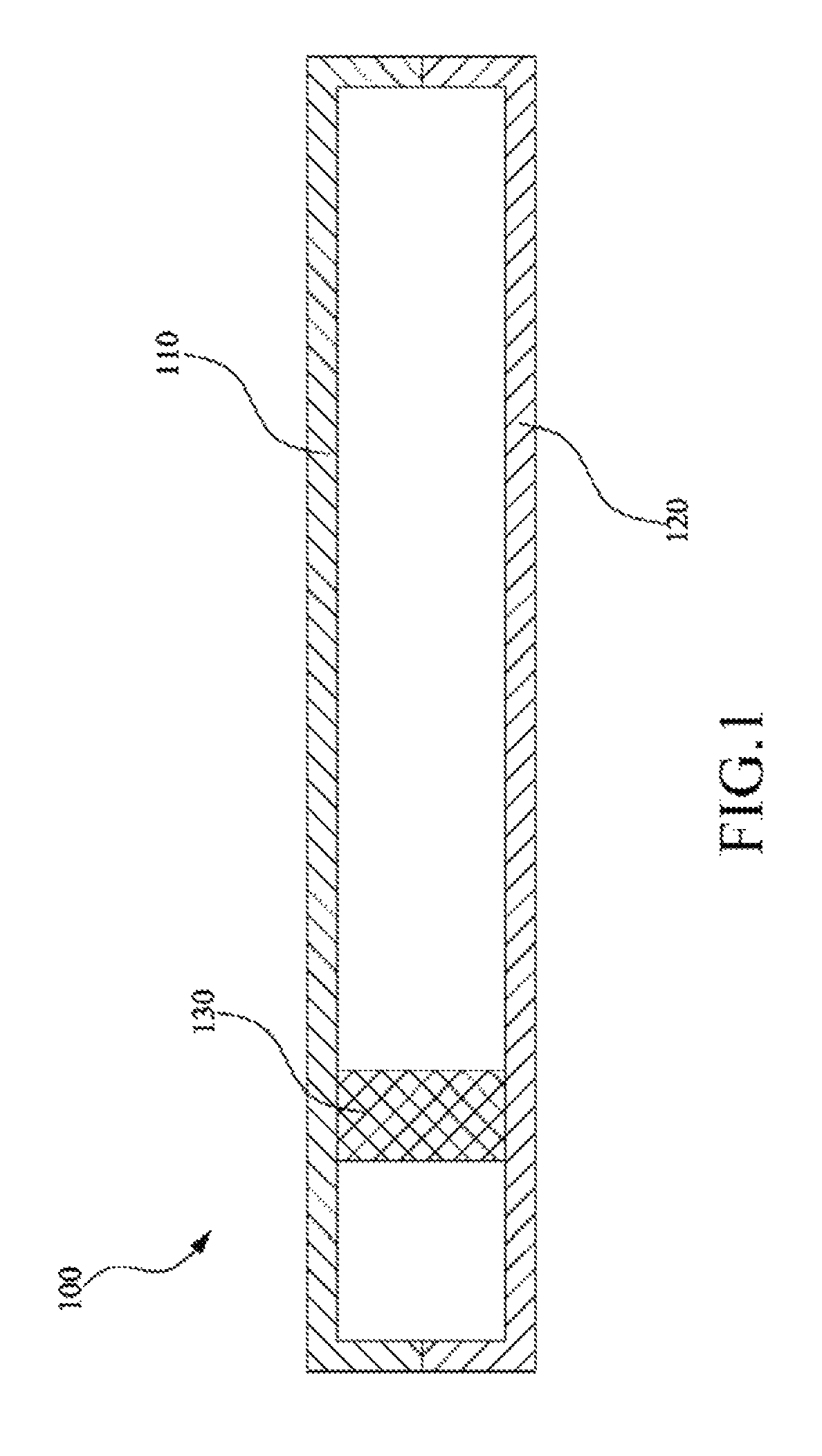
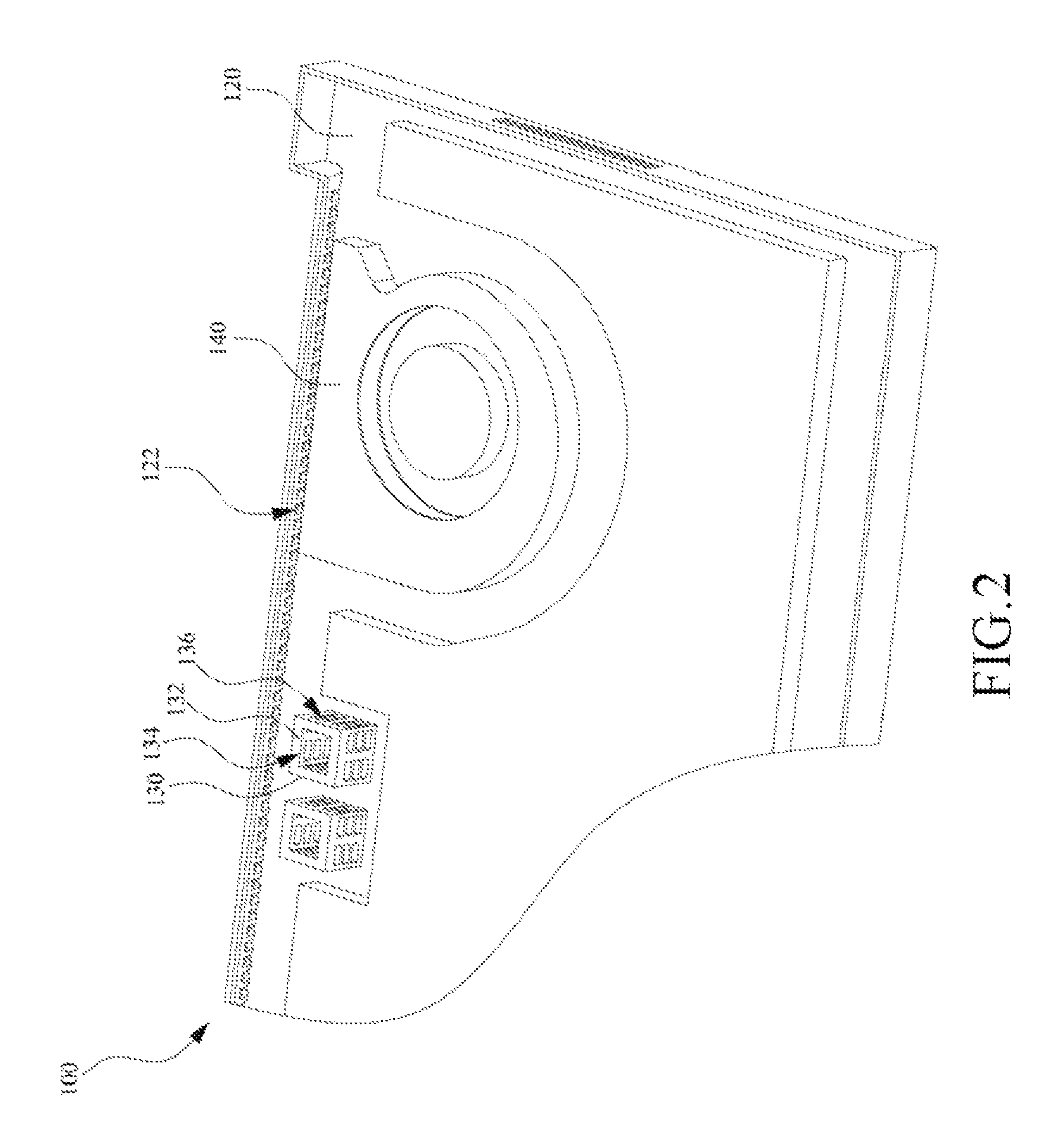
[0013]FIG. 1 is a sectional schematic diagram showing an electronic device 100 in one embodiment. The electronic device 100 includes an upper cover 110, a lower cover 120 and a heat conducting pillar 130. The upper cover 110 and the lower cover 120 are combined with each other to form a casing of the electronic device 100, and an accommodating space is formed between the upper cover 110 and the lower cover 120. The heat conducting pillar 130 is disposed in the accommodating space and physically connected with the upper cover 110 and the lower cover 120 to balance the temperature of the upper cover 110 and the lower cover 120.

[0014]In the electronic device 100, since the configurations and positions of heat generating elements are various, one of the upper cover 110 and the lower cover 120 usually has a higher temperature. The heat conducting pillar 130 connecting the upper cover 110 and the lower cover 120 conducts the heat from one of the upper cover 110 and the lower cover 120 wit...


PUM


Abstract

An electronic device includes an upper cover, a lower cover combined with the upper cover, and a heat conducting pillar. An accommodating space is formed by the upper cover and the lower cover. The heat conducting pillar is disposed in the accommodating space and physically connected with the upper cover and the lower cover to balance the temperature of the upper cover and the lower cover.

Description

CROSS-REFERENCE TO RELATED APPLICATION[0001]This application claims the priority benefit of CN application serial NO. 201210491297.7, filed on Nov. 27, 2012. The entirety of the above-mentioned patent application is hereby incorporated via reference herein and made a part of specification.BACKGROUND OF THE INVENTION[0002]1. Field of the Invention[0003]This disclosure relates to an electronic device and, more particularly to a portable electronic device.[0004]2. Description of the Related Art[0005]A processor of an electronic device can generate heat in operation. While the heat generated by the processor cannot be dissipate, the electronic device may work in unstable state. Thus, the electronic device needs a heat dissipation module to enhance the heat dissipation effect.[0006]With the development of science, more portable electronic, devices such as a notebook, a tablet computer or a smartphone are commonly used in daily life. Since the development trend of appearance of portable e...

Claims


Application Information

Patent Timeline
Patent Type & Authority Patents(United States)
IPC IPC(8): H02B1/00G06F1/20F28D15/00F28F7/00H01L23/34H05K5/00H01R13/46H05K1/00H05K7/20H02B1/56F28D15/02F04D29/40
CPCH05K7/20G06F1/20G06F1/203H05K7/20145H05K7/20445F04D29/40F28D15/02
Inventor NIU, CHIA-CHINGCHIOU, ING-JERWANG, CHENG-YU
Owner ASUSTEK COMPUTER INC
Why Eureka
Try Eureka