Multi-directional thorax wall stabilisation

a multi-directional, thoracic wall technology, applied in the field of implants, can solve the problems of large surgical trauma, patient remains, and relatively large procedure, and achieve the effect of reducing the risk of fracture, and improving the stability of the thoracic wall

Active Publication Date: 2016-04-19
MEDXPERT GMBH
View PDF9 Cites 13 Cited by
  • Summary
  • Abstract
  • Description
  • Claims
  • Application Information

AI Technical Summary

Benefits of technology

[0011]Preferably, the clamp has a fillet which has a longitudinal axis and at least a first prong, a second prong and a third prong, wherein the prongs extend from the fillet transversely (especially perpendicularly) to the longitudinal axis, and the first and third prongs are disposed relative to the longitudinal axis on a first side of the fillet, and the second prong is disposed relative to the longitudinal axis on a second side of the fillet. The prongs are disposed in a staggered arrangement, relative to the longitudinal axis. In particular, the prongs are disposed in a staggered arrangement such that they are laterally offset from each other. In this way, the free ends of the prongs can engage with each other when compressed with a tool and do not hinder each other.
[0014]Especially, the sections of the prongs connected to the fillet extend transversely and / or perpendicularly outwards, relative to the longitudinal axis. The end sections of the prongs facing away from the fillet may also be bent down and out from a plane, which is determined by the fillet, such that the implant can be relatively easily applied to a rib bone and then the prongs can be bent at least partially around the rib bone by a tool. In this way, the fillet and prongs form a clamp.
[0015]Preferably, the thickness of the material of the second prong (along with the thickness of the material of any further prongs disposed on the second side and gripped by the tool) is set such that the resistance to bending corresponds to the sum of the resistance to bending of the first and the third prongs (together with the resistance to bending of any further prongs disposed on the first side and gripped by the tool). This prevents the clamp from rotating in the tool during attachment to the rib bone.

Problems solved by technology

This leads to considerable surgical trauma, and the patient must remain in the hospital for some time.
The procedure is therefore relatively extensive and generally leaves a clearly visible scar.

Method used


Image

  • Multi-directional thorax wall stabilisation
  • Multi-directional thorax wall stabilisation
  • Multi-directional thorax wall stabilisation

Examples


Embodiment Construction

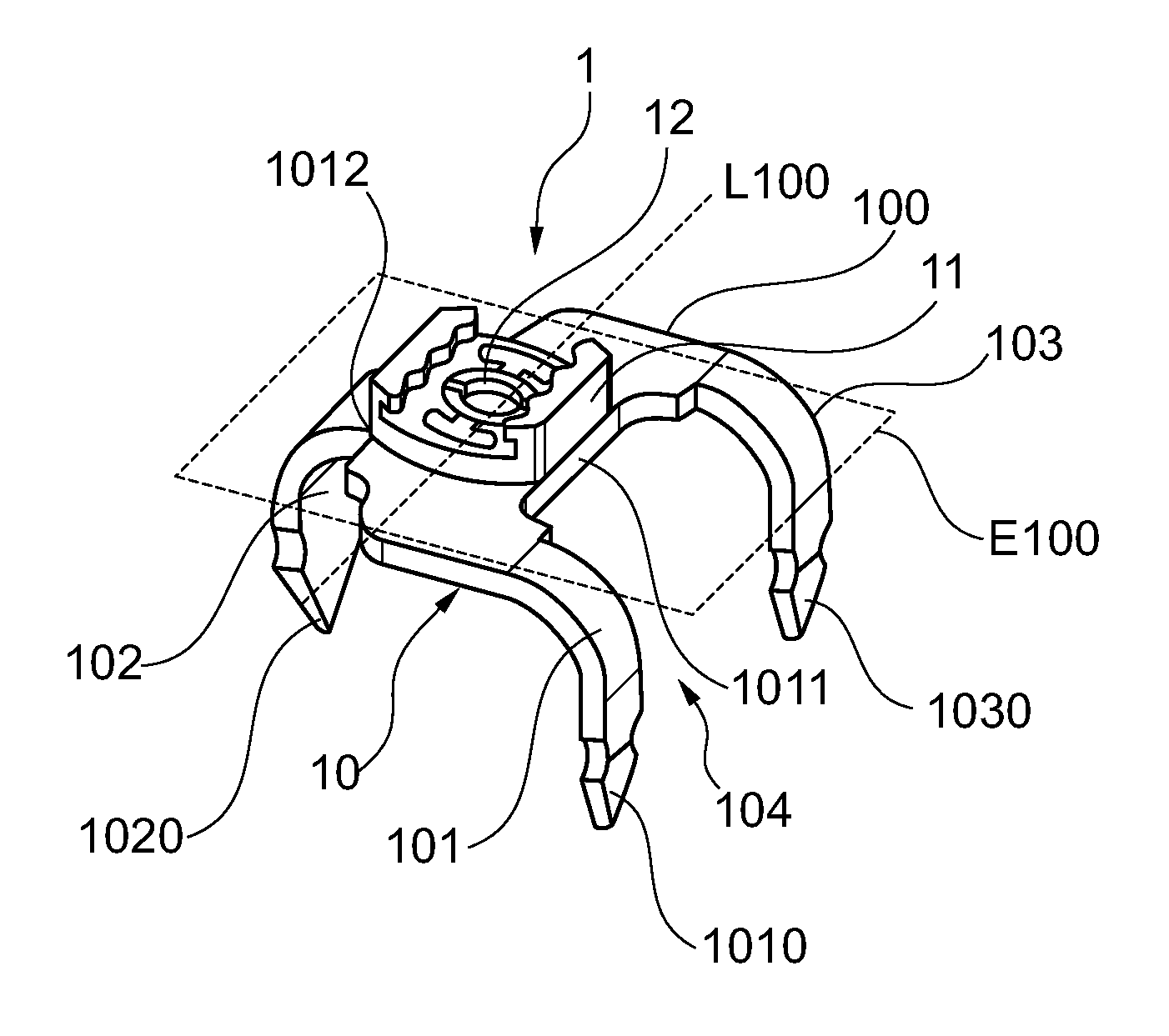
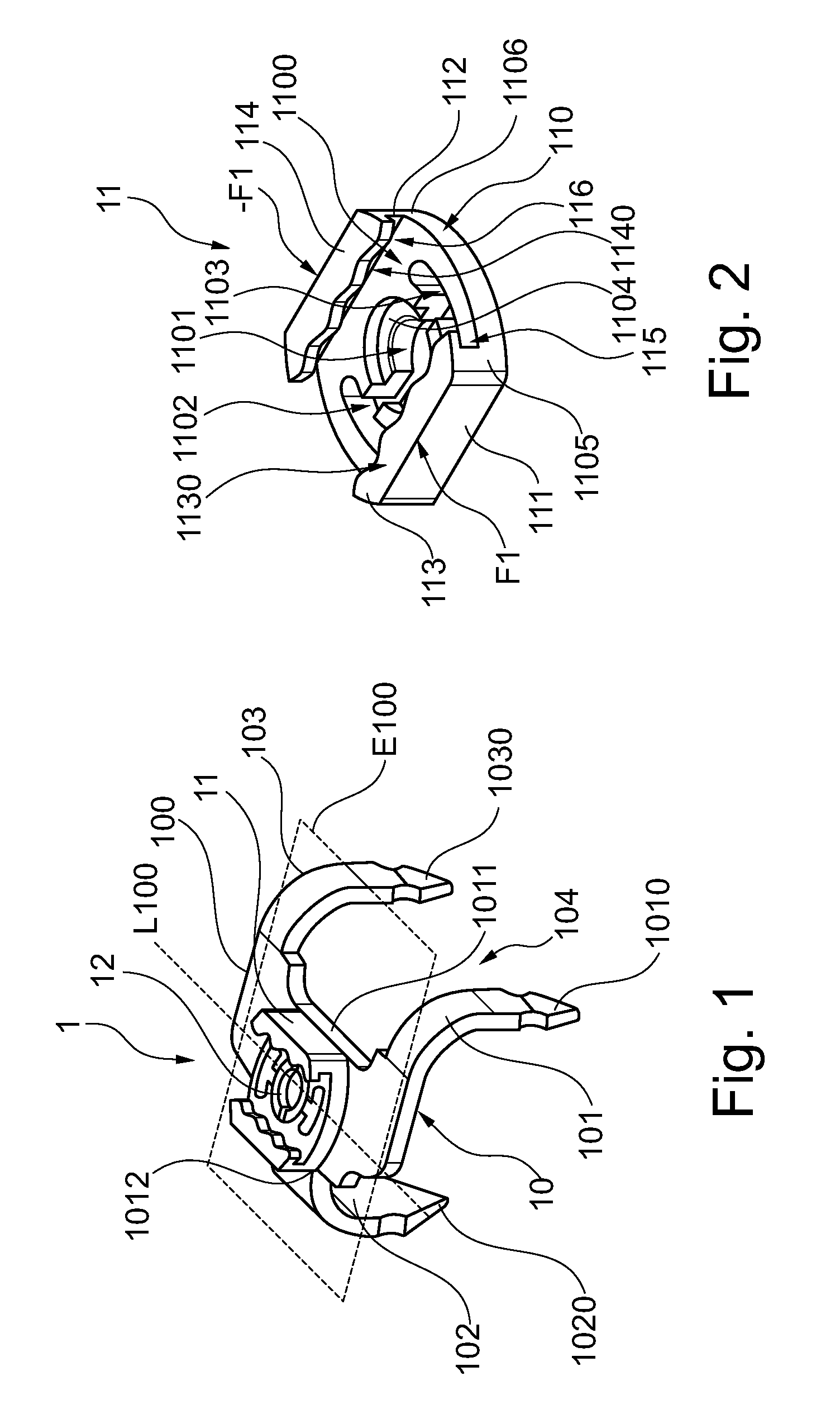
[0035]FIG. 1 shows a perspective view of a first embodiment of a first implant 1 in accordance with the present invention.

[0036]The first implant 1 has a clamp 10. This comprises a fillet 100 and prongs 101, 102, 103 extending from both sides of the fillet 100. The first prong 101 and the third prong 103 are (in the longitudinal direction L100 of the fillet) spaced apart from each other on a first side 1001 of the fillet 100, the second prong 102 is disposed on a second side 1002 opposite the first side 1001. The prongs 101, 102, 103 extend outwardly from the fillet 100 and roughly perpendicularly to the longitudinal axis L100 of the fillet 100 and are bent down and out from the plane E100 formed by the fillet 100. The prongs 101, 102 and 103 are disposed so as to be offset from one another on the fillet 100, relative to the longitudinal axis L100 of the fillet 100. In this connection, the second prong 102 is disposed at the level of the gap 104 between the first prong 101 and the t...


PUM


Abstract

An implant (1) for attaching the first implant (1) to a tubular bone, in particular a rib bone, includes: a clamp (10) having a fillet (100) and prongs (101, 102, 103) extending from the fillet (100); and a first connecting element (11) for connecting the first implant (1) to a connector implant. The clamp (10) and the connecting element (11) are connected so as to be rotatable relative to each other about an axis.

Description

TECHNICAL FIELD[0001]The present invention relates to a first implant for the attachment of the implant to a tubular bone, in particular a rib bone, comprising: a clamp having a fillet and prongs extending from the fillet; and a connecting element for connecting the implant to a connector implant. The present invention also relates to a first implant for the attachment of the implant to a tubular bone, in particular a rib bone, comprising: a clamp having a fillet which has a longitudinal axis and comprising at least a first prong, a second prong and a third prong, wherein the prongs extend from the fillet transversely to the longitudinal axis, and the first and third prongs are disposed relative to the longitudinal axis on a first side of the fillet, and the second prong is positioned relative to the longitudinal axis on a second side of the fillet. The invention also relates to a second implant for connecting two connector implants of an implant system, comprising: a fillet, a firs...

Claims


Application Information

Patent Timeline
Patent Type & Authority Patents(United States)
IPC IPC(8): A61B17/04A61B17/84A61F2/08A61B17/80A61B17/82
CPCA61B17/823A61B17/8076A61B17/8085A61B17/707
Inventor REISBERG, ERHARD
Owner MEDXPERT GMBH
Why Eureka
Try Eureka