Arm for construction machine with upper ends of rear plate protruding upward

a construction machine and rear plate technology, applied in the direction of cranes, lifting devices, constructions, etc., can solve the problems of deterioration of the durability of the entire arm including the thickness of the upper plate and the lower plate is too large for the required strength, and the overall weight of the entire arm becomes larger than necessary, so as to improve the strength of the arm cylinder bracket itself against the load, the effect of joint strength and relatively low rigidity

Active Publication Date: 2016-04-19
NIHON KENKI CO LTD
View PDF8 Cites 2 Cited by
  • Summary
  • Abstract
  • Description
  • Claims
  • Application Information

AI Technical Summary

Benefits of technology

[0010]In view of the above-described conventional art problem, it is an object of the present invention to provide an arm for a construction machine which can reduce the weight of the entirety while ensuring required strength.
[0013]With this arrangement, by arranging the upper ends of the pair of arm cylinder brackets higher than the height position of the outer surface of the upper plate and lower than the upper end of the rear plate, a facing area facing the rear plate, that is, a joint area of each of the arm cylinder brackets can be formed large. As a result, strength of each of the arm cylinder brackets itself against the load can be improved. On the other hand, a welding length between each of the arm cylinder brackets and the rear plate can be ensured large, and joint strength of each of the arm cylinder brackets to the rear plate can be improved.
[0014]Moreover, by protruding the upper end of the rear plate upward from the height position of the outer surface of the upper plate, its rigidity becomes relatively low, and in the upper end side of the rear plate, appropriate deflection is generated in accordance with a load acting on the upper end portion of the arm cylinder bracket. Thus, the load acting on the upper end portion of the arm cylinder bracket can be absorbed by deflection on the upper end side of the rear plate and concentration of stress generated in the joint portion (welding stop end portion) between the upper end of the arm cylinder bracket and the rear plate can be reduced. As a result, plate thickness of each of the arm cylinder brackets can be made smaller, while joint strength of the pair of arm cylinder brackets to the rear plate is ensured, and weight reduction of the entire arm can be realized.
[0016]With this arrangement, by applying fillet welding between the groove provided on an end surface of each of the arm cylinder brackets and the outer surface of the rear plate, each of the arm cylinder brackets can be sufficiently blended in the plate thickness direction and can be firmly joined to the outer surface of the rear plate. As a result, joint strength of the pair of arm cylinder brackets to the rear plate can be further improved, and durability of the arm cylinder bracket can be improved.

Problems solved by technology

Thus, on the front side of the arm, the plate thicknesses of the upper plate and the lower plate tend to be too large for the required strength, and there is a problem that a weight of the entire arm becomes larger than necessary.
However, the arm cylinder bracket is joined to the rear plate provided on the rear end of the arm by welding, and a large load accompanying extension / contraction of the arm cylinder acts on this arm cylinder bracket.
As a result, there is a problem that durability of the entire arm including the arm cylinder bracket deteriorates.

Method used


Image

  • Arm for construction machine with upper ends of rear plate protruding upward
  • Arm for construction machine with upper ends of rear plate protruding upward
  • Arm for construction machine with upper ends of rear plate protruding upward

Examples


Embodiment Construction

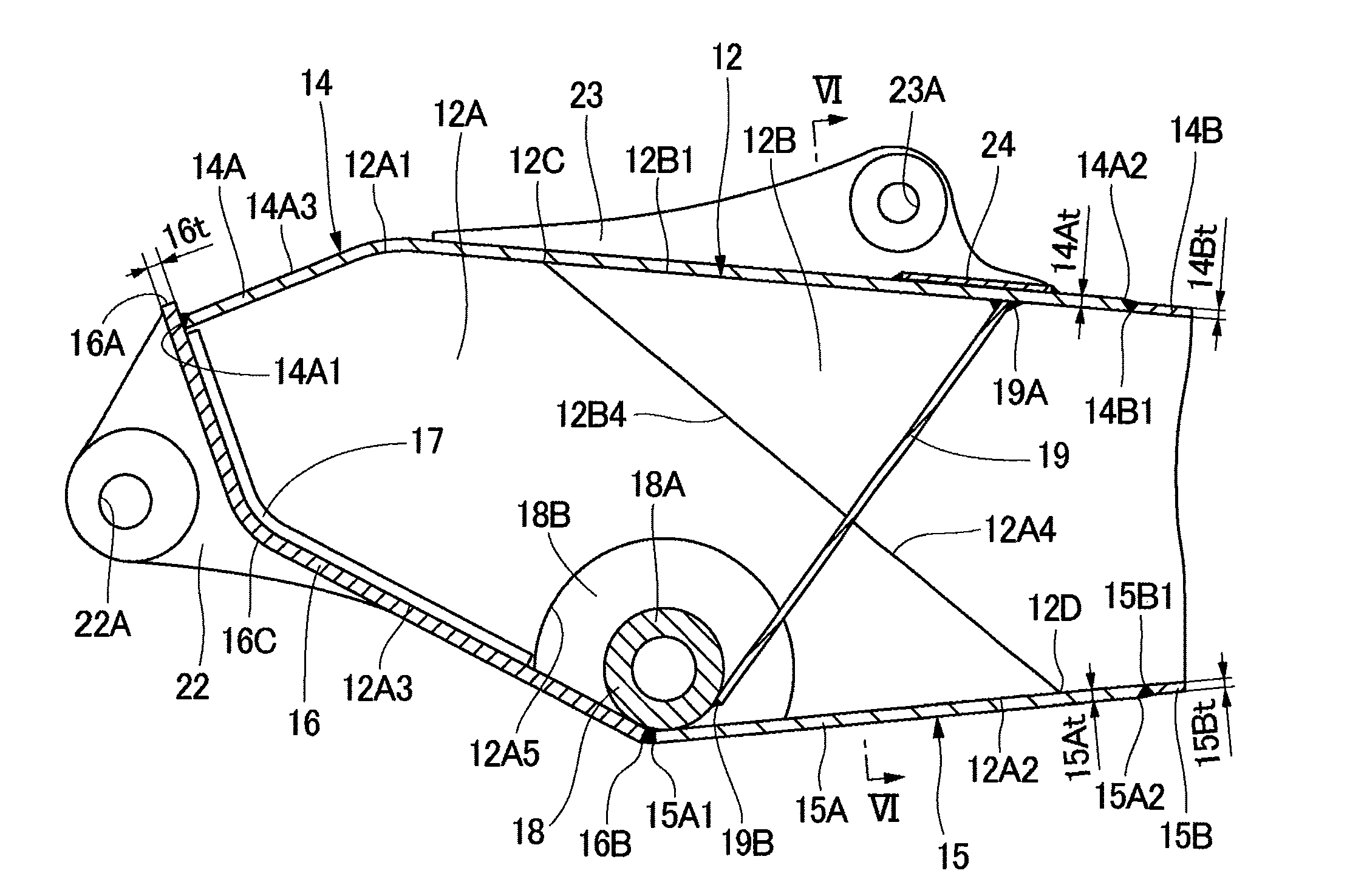
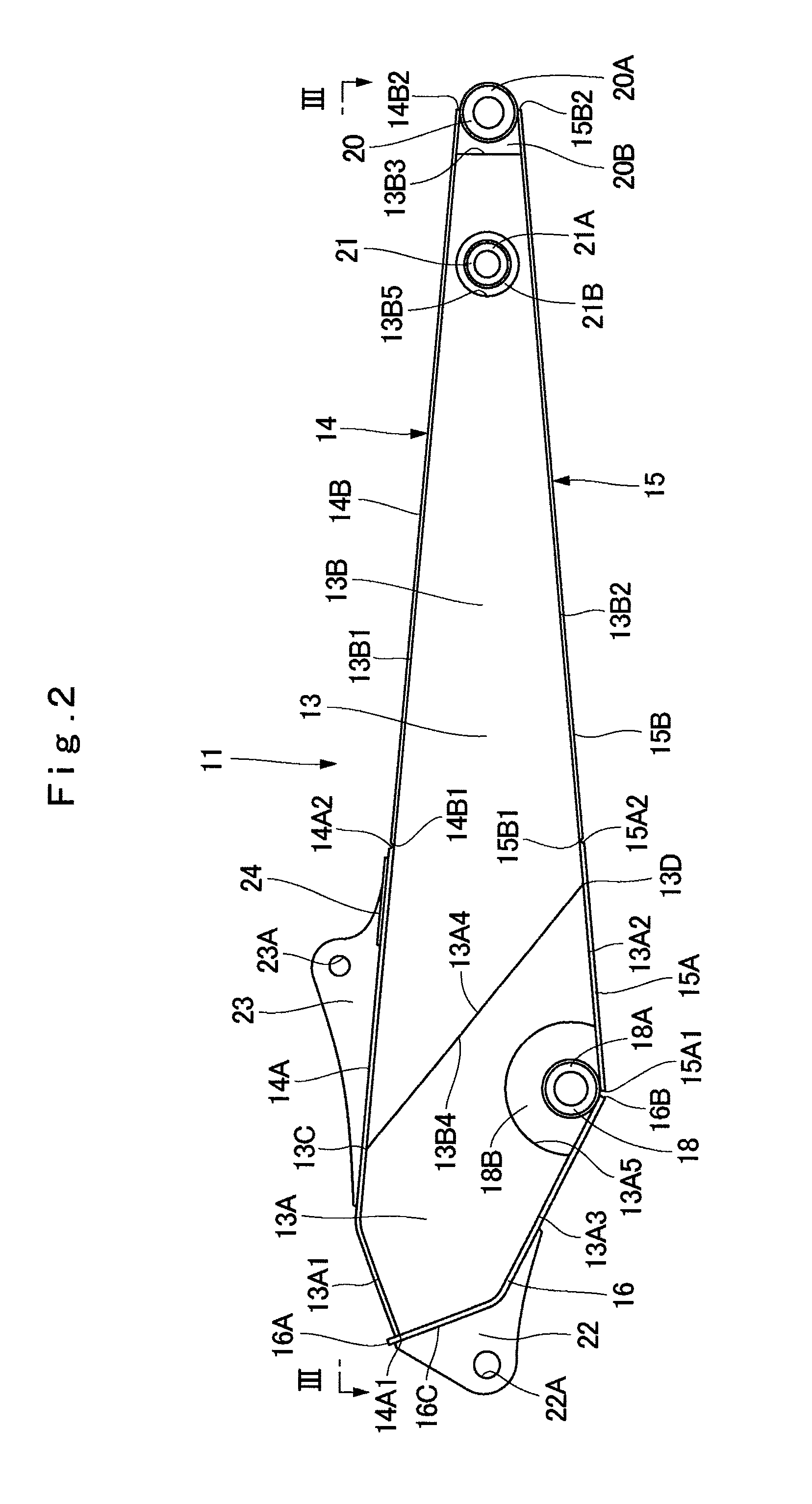
[0031]Hereinafter, an embodiment of an arm for a construction machine according to the present invention will be described below in detail with reference to the accompanying drawings by using a case applied to an arm of a hydraulic excavator as an example.

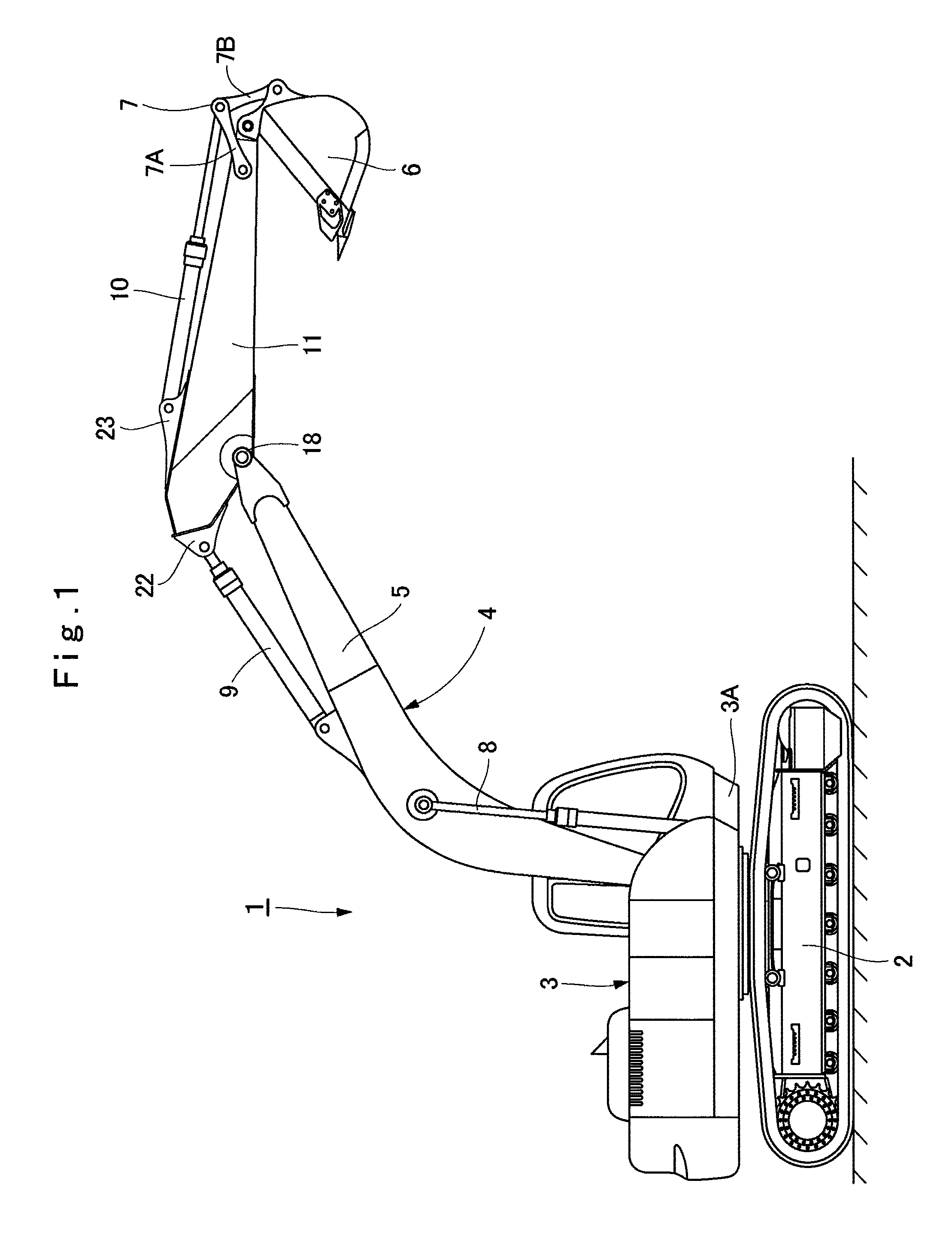
[0032]Designated at 1 is a hydraulic excavator as a typical example of a construction machine in the drawing, and the hydraulic excavator 1 is provided with an automotive crawler-type lower traveling structure 2 and an upper revolving structure 3 rotatably mounted on the lower traveling structure 2. A working mechanism 4 is provided capable of moving upward / downward on the front part side of a revolving frame 3A which becomes a base of the upper revolving structure 3.

[0033]The working mechanism 4 is provided with a boom 5 having a base end portion pin-connected to the front part side of the revolving frame 3A capable of moving upward / downward, an arm 11 which will be described later having a base end portion rotatably pin-connected...


PUM


Abstract

An arm of a hydraulic excavator is formed as a box-shaped structural body surrounded by left and right side plates, an upper plate, a lower plate, and a thick rear plate. An upper end of the thick rear plate is protruded upward from an outer surface of the upper plate. Upper ends of a pair of arm cylinder brackets joined to an outer surface of the thick rear plate are arranged higher than the outer surface of the rear thick upper plate and lower than the upper end of the thick rear plate. As a result, in each of the arm cylinder brackets, a joint area with the thick rear plate can be ensured large, and joint strength can be improved.

Description

TECHNICAL FIELD[0001]The present invention relates to an arm for construction machine suitably used in a working mechanism mounted on a construction machine such as a hydraulic excavator and the like, for example.BACKGROUND ART[0002]In general, a hydraulic excavator which is a typical example of a construction machine is composed of an automotive lower traveling structure and an upper revolving structure rotatably mounted on the lower traveling structure. On the front side of a revolving frame constituting the upper revolving structure, a working mechanism performing excavating work of earth and sand and the like is provided capable of moving upward / downward.[0003]Here, the working mechanism of a hydraulic excavator is usually composed largely of a boom having the base end side rotatably mounted on the revolving frame, an arm rotatably mounted on the distal end side of the boom, a working tool such as a bucket or the like rotatably mounted on the distal end side of the arm, and a bo...

Claims


Application Information

Patent Timeline
Patent Type & Authority Patents(United States)
IPC IPC(8): E02F3/38
CPCE02F3/38
Inventor SUGAYA, MAKOTOTAKAHASHI, TAKESHISHIMODAIRA, TAKAYUKI
Owner NIHON KENKI CO LTD
Why Eureka
Try Eureka