Guide device for coiled tubing

a coiled tubing and guide device technology, applied in the oil field, can solve the problems of wasting expensive coiled tubing, inconvenient use, flexibility in operation, etc., and achieve the effects of reducing the overall weight, enhancing operability and convenience, and fast and safe pulling of coiled tubing

Active Publication Date: 2016-04-19
BC P INC CHINA NAT PETROLEUM CORP +2
View PDF6 Cites 4 Cited by
  • Summary
  • Abstract
  • Description
  • Claims
  • Application Information

AI Technical Summary

Benefits of technology

[0006]The present invention is directed to a coiled tubing guide-in device, which uses power source provided by an injector head motor of a coiled tubing unit, and is capable of fast and safely pulling a coiled tubing out of a tubing reel, and guiding the coiled tubing into injector head gripper blocks through a guider. Creative structural improvement is achieved based on the two existing coiled tubing guide-in tools, and advantages of the two existing tools are integrated, so as to enhance the operability and convenience and reduce the overall weight while ensuring sufficient flexibility and rigidity. Moreover, after the coiled tubing is guided into the injector head, the coiled tubing guide-in device and the connection joint are removed quickly and conveniently without damaging the coiled tubing.
[0013]The guide head consists of the spherical support body, the inner conical sleeve, the outer conical clamping sleeve, the preloaded nut and the conical guide body. The structure of the guide head is substantially the same as that of the locking sleeve, and a difference is that the conical guide body is conical, an upper outer diameter of the conical guide body is the same as an outer diameter of the spherical support body, and a lower end of the conical guide body is provided with a convex spherical body. The conical guide body is provided with a center hole, and the traction steel rope passes through the center hole of the conical guide body. The conical guide body is capable of smoothly guiding the traction body into the gripper blocks.

Problems solved by technology

The deficiency thereof lies in that, after the coiled tubing is guided into the injector head, the snake-rope guide-in device cannot be taken down until the connection joint and the coiled tubing head are cut off, which wastes the expensive coiled tubing and causes inconvenience in use.
In addition, for a coiled tubing with a great diameter (the diameter above 2⅜″), such a snake-rope guide-in device provides poor flexibility in operation, which directly affects the pipe guide efficiency.
The guide-in device becomes clumsy, increases the labor intensity of workers, and is inconvenient to operate.
The winch coiled tubing guide-in device provides desirable flexibility and reduces the labor intensity of workers, however, it requires an external power source and is inconvenient to use on site.

Method used


Image

  • Guide device for coiled tubing
  • Guide device for coiled tubing
  • Guide device for coiled tubing

Examples


embodiment 1

[0025]A coiled tubing guide-in device of with the specification of 2⅜″ is used as an example to further describe the present invention in detail.

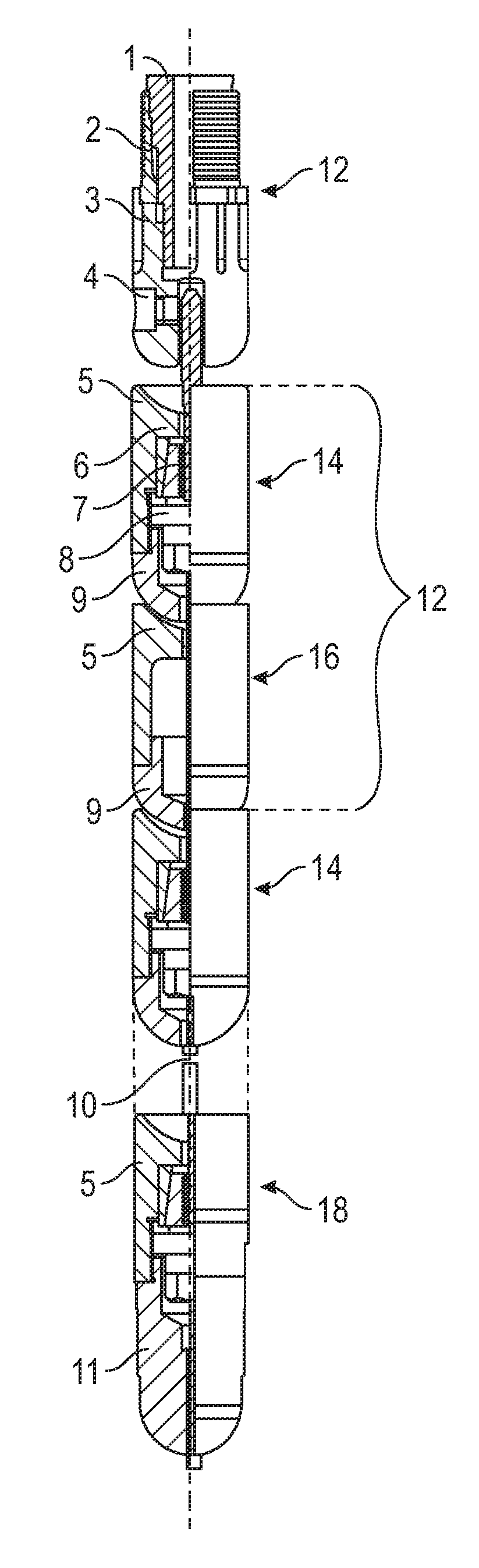
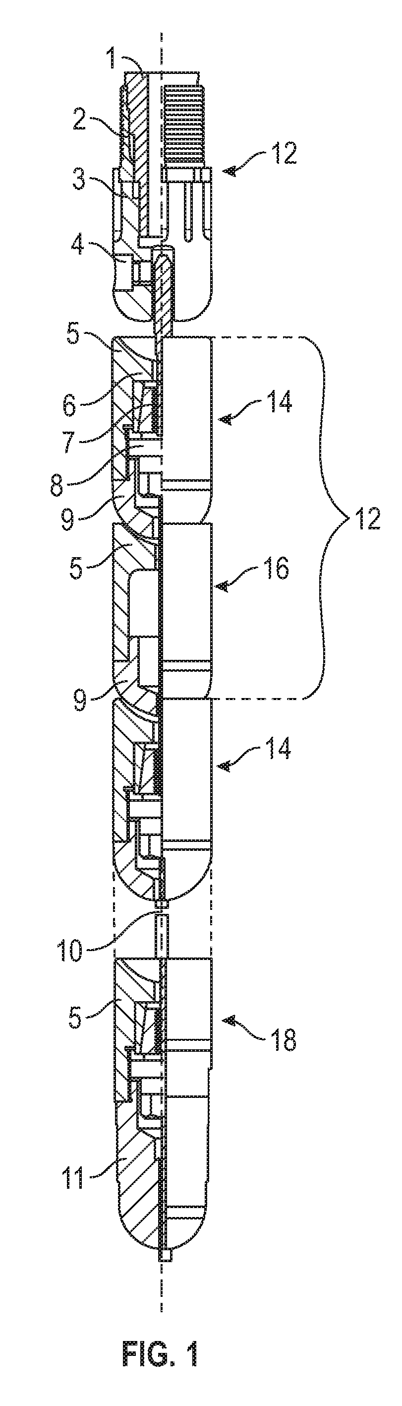
[0026]Referring to FIG. 1, the coiled tubing guide-in device of the present invention mainly consists of a slip connecting head 12, a locking sleeve 14, a floating sleeve 16, a guide head 18, and a traction steel rope 10.

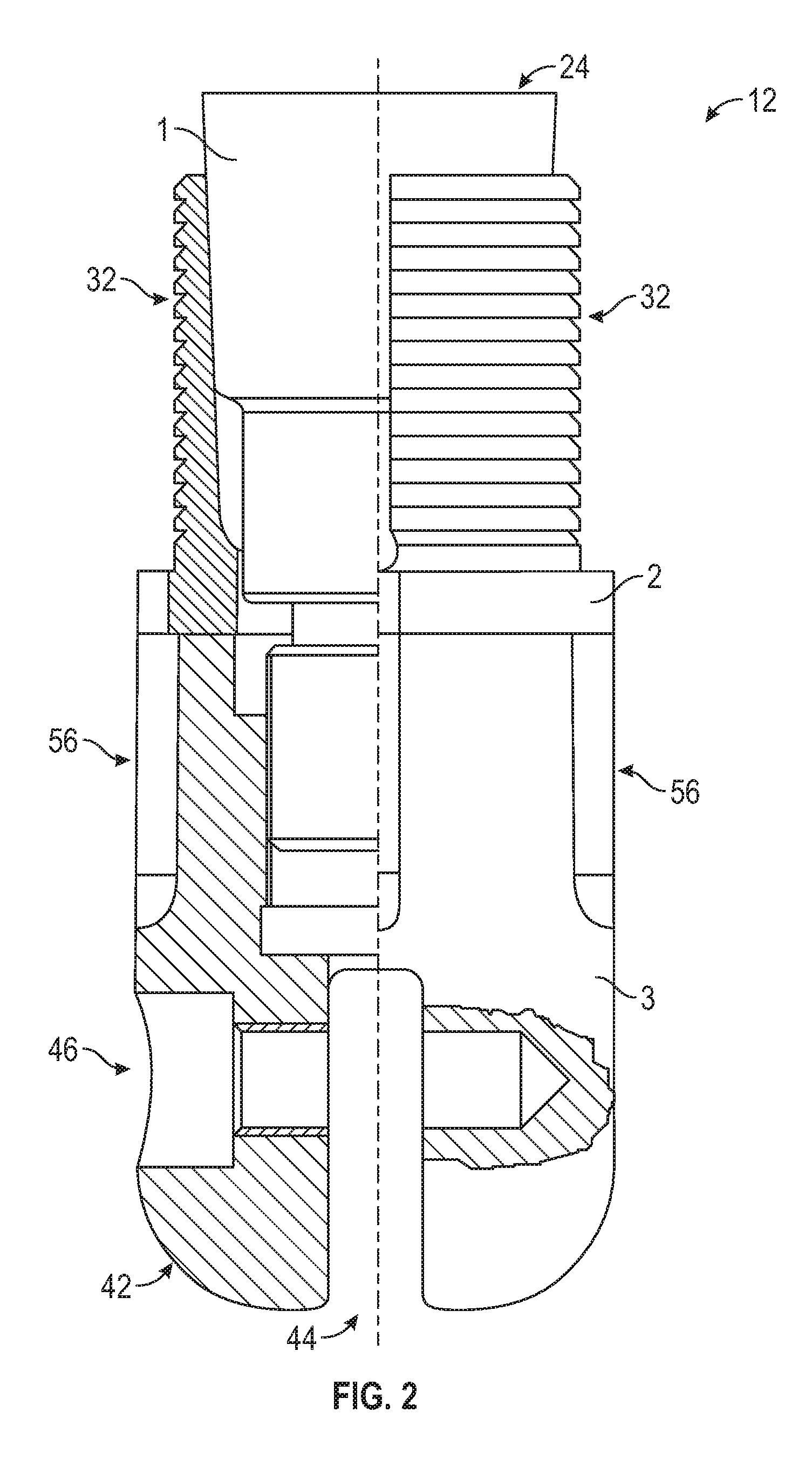
[0027]The slip connecting head 12 mainly consists of an expansion plug 1, a slip sleeve 2, and a tightening nut 3. The expansion plug 1 consists of a cone 20 and screw thread body 22. The cone 20 is connected with the screw thread body 22. Center lines of the cone 20 and the screw thread body 22 are on the same straight line. A major diameter end 24 of the cone 20 at an end of the expansion plug 1 is at an external end, that is, a minor diameter end 26 of the cone 20 is connected to an end of the screw thread body 22 of the expansion plug 1, and the screw thread body 22 is cylindrical and is provided with trapezoid external...


PUM


Abstract

A coiled tubing guide-in device is applied to oil field coiled tubing operation and used for guiding a coiled tubing into injector head gripper blocks. The coiled tubing guide-in device mainly consists of a slip connecting head, a locking sleeve, a floating sleeve, a guide head, and a traction steel rope. In the structure of the slip connecting head, a cone of an expansion plug is arranged in a slip sleeve. A lower end of a tightening nut is a convex spherical body. At a lower end of the tightening nut, an end of a traction steel rope is fixed in a rectangular groove at the lower end of the tightening nut through a threaded pin. In the structure of the locking sleeve, an upper end surface of a spherical support body is a concave spherical surface. An inner conical sleeve and an outer conical clamping sleeve are arranged in a cylindrical space. A spherical head is fixed on inner screw threads of the spherical support body. The number of combined locking bodies ranges from 4 to 15. A lower end of the floating sleeve at the lowest end is connected with a conical guide body through the traction steel rope. The effect is that the coiled tubing is fast and safely pulled out of a tubing reel and guided into the injector head gripper blocks through a guider.

Description

BACKGROUND OF THE INVENTION[0001]1. Field of Invention[0002]The present invention relates to the technical field of oil field coiled tubing operation, and in particular, to a dedicated coiled tubing guide-in tool, namely, a coiled tubing guide-in device, capable of pulling a coiled tubing out of a tubing reel and guiding the coiled tubing into injector head gripper blocks.[0003]2. Related Art[0004]Currently, a coiled tubing unit is dedicated equipment used for oil-gas well operation, which mainly consists of a tubing reel (coiling coiled tubing), an injector head (which clamps the coiled tubing through the gripper blocks and injects the coiled tubing into the oil-gas well or lifts the coiled tubing out of the oil-gas well), and a power control system. During an installation process of the device at the well site, the coiled tubing on the tubing reel must be pulled out and inserted into the injector head gripper blocks before the subsequent installation operations are performed. Howe...

Claims


Application Information

Patent Timeline
Patent Type & Authority Patents(United States)
IPC IPC(8): E21B19/24E21B19/22
CPCE21B19/24E21B19/22
Inventor ZHANG, SANPOLIU, TIELIZHU, ZAISIWU, DAFEILUO, GANG
Owner BC P INC CHINA NAT PETROLEUM CORP
Why Eureka
Try Eureka