
Remote pendant with extended user interface

a remote operator and user interface technology, applied in the field of machine tools, can solve the problems of cumbersome use of the operator panel attached to the machine,

Active Publication Date: 2016-05-03
GLEASON METROLOGY SYST CORP
View PDF6 Cites 5 Cited by
  • Summary
  • Abstract
  • Description
  • Claims
  • Application Information

AI Technical Summary

Benefits of technology

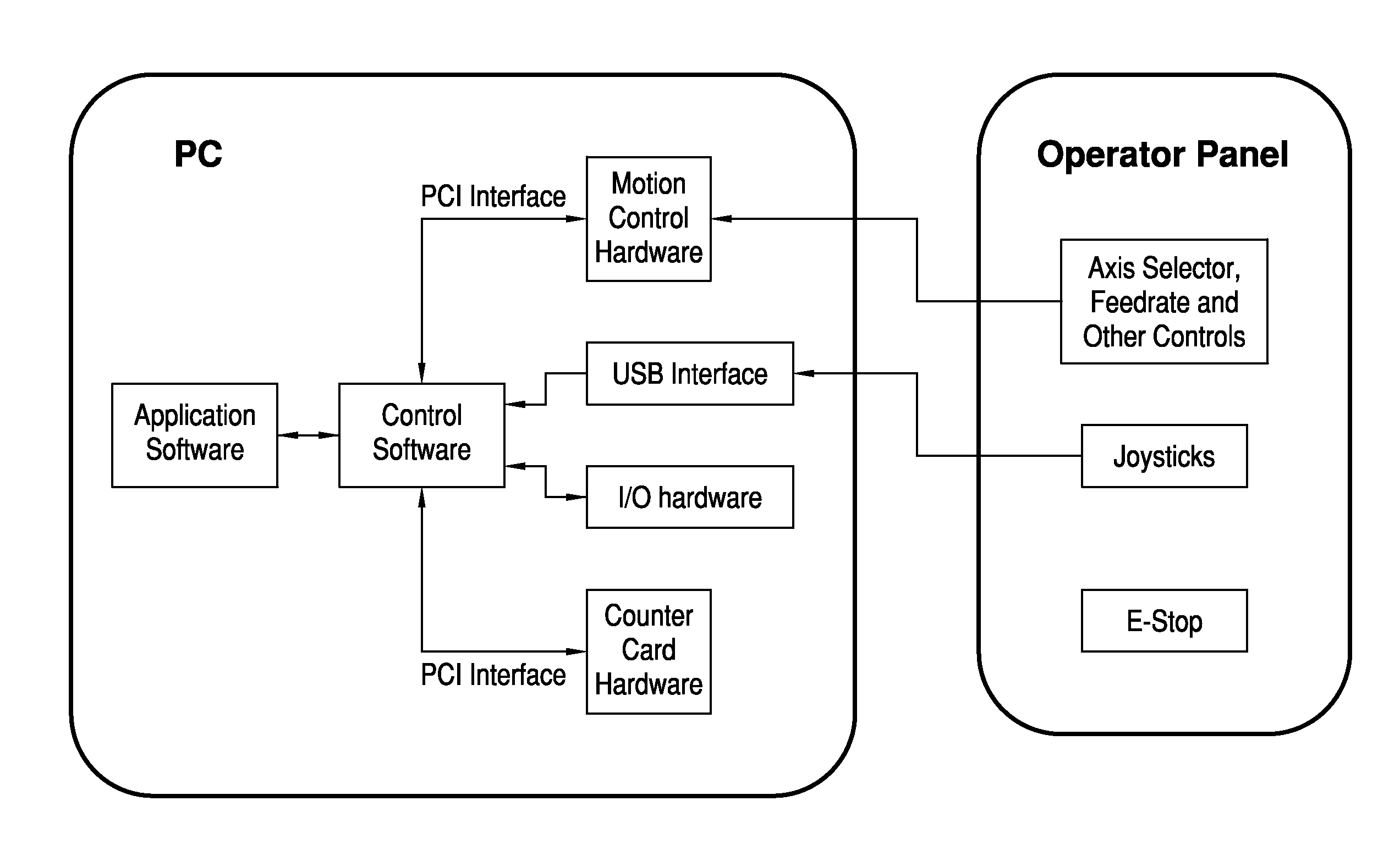
[0013]The present invention is directed to a remote pendant for a metrology machine. The pendant comprises a non-configurable user interface which is an extension of the main computer monitor wherein the screens shown on a monitor of the pendant are created by application and / or control software running on the PC of the machine. The remote pendant further comprises camera and / or webcam features as well as voice recording capabilities. With the remote pendant, the machine operator can view messages appearing on the main computer screen and respond to any prompts via a touch screen on the pendant thereby eliminating the need to return to the machine operator station.

Problems solved by technology

As the machine size increases, the operator often will have to climb on the machine to access the gear on the rotary table.
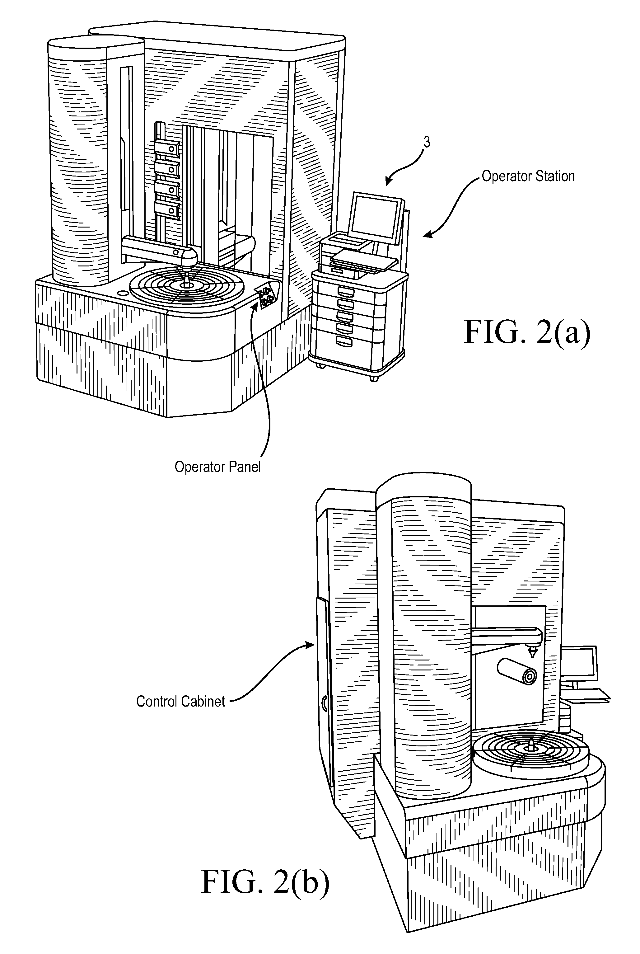
An operator panel attached to the machine is cumbersome to use in such instances and there is a need for a remote pendant that the operator can carry along and use for jogging the machine axes as needed.

Method used


Image

  • Remote pendant with extended user interface
  • Remote pendant with extended user interface
  • Remote pendant with extended user interface

Examples


Embodiment Construction

[0029]Before any features and at least one construction of the invention are explained in detail, it is to be understood that the invention is not limited in its application to the details of construction and the arrangements of the components set forth in the following description or illustrated in the drawings. The invention is capable of other constructions and of being practiced or being carried out in various ways. Also, it is understood that the phraseology and terminology used herein is for the purposes of description and should not be regarded as limiting.

[0030]FIGS. 6-9 show a remote pendant 20 of the present invention preferably comprising two joy sticks 22, 24, an E-Stop 26 and a touch screen monitor 28 (e.g. 7 inch monitor). A webcam 30 (FIGS. 8 and 9) with a microphone is preferably integrated into the remote pendant 20. The microphone is preferably located in the face 31 of the camera 30 and may take the form of one or more small openings in the face of the camera. Pre...


PUM


Abstract

A remote pendant for a metrology machine. The pendant comprises a non-configurable user interface which is an extension of the main computer monitor wherein the screens shown on a monitor of the pendant are created by application and / or control software running on the computer control of the machine. The remote pendant further comprises camera and / or webcam features as well as voice recording capabilities. With the remote pendant, the machine operator can view messages appearing on the main computer screen and respond to any prompts via a touch screen on the pendant thereby eliminating the need to return to the machine operator station.

Description

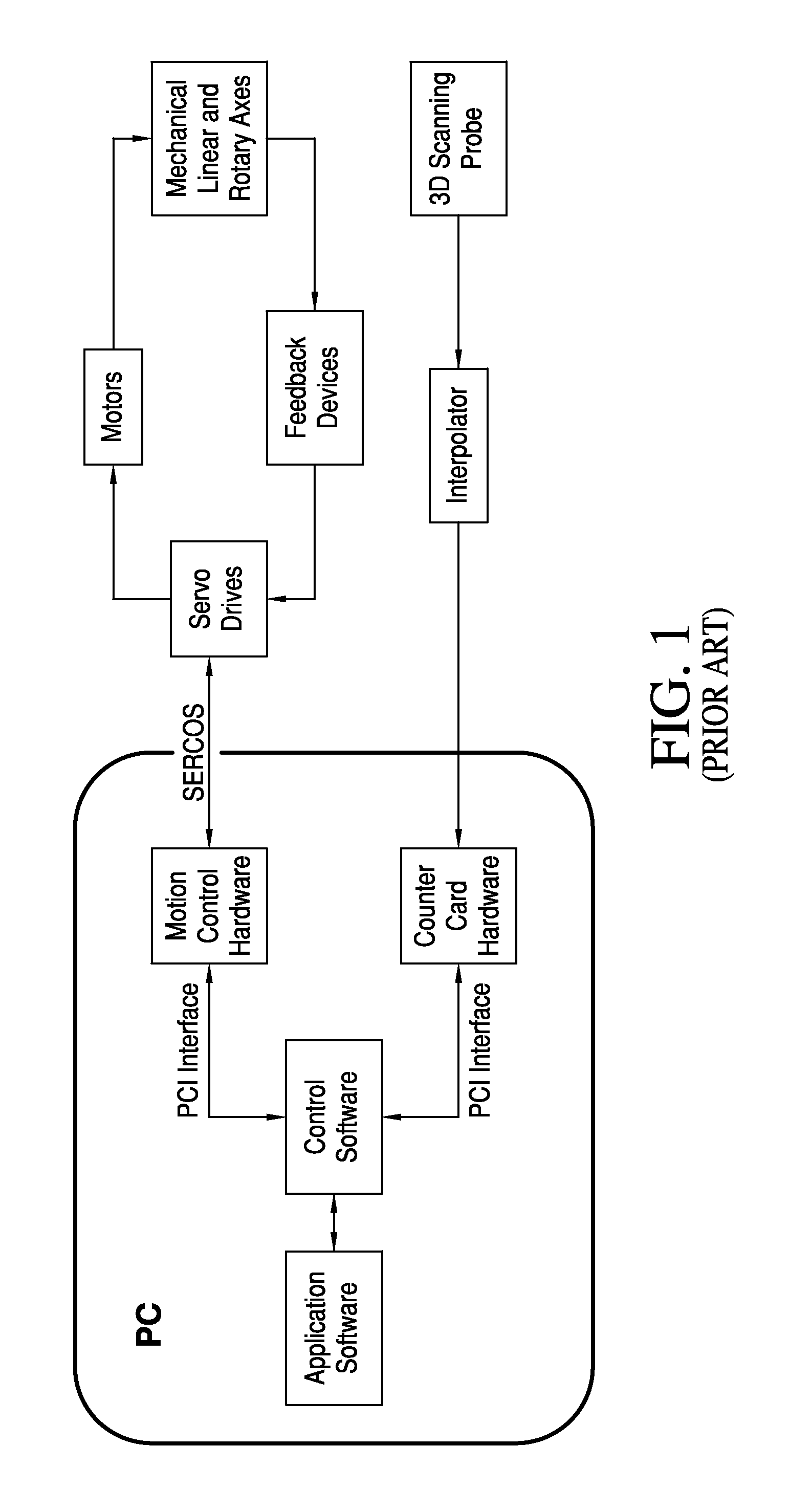
[0001]This application claims the benefit of U.S. Provisional Patent Application No. 61 / 381,588 filed Sep. 10, 2010, the entire disclosure of which is hereby incorporated by reference.FIELD OF THE INVENTION[0002]The present invention is directed to machine tools, in particular to metrology machines such as gear metrology machines, and to a remote operator pendant for such machine tools.BACKGROUND OF THE INVENTION[0003]Today, most metrology machines for gears (and other toothed articles) and / or gear cutting tools comprise a computer-controlled electro-mechanical multi-axis system. FIG. 1, for example, shows the architecture of a known metrology system. The application software (for example, GAMA software commercially available from Gleason Metrology Systems) provides the interface to the end user to program the gear parameters, select tests and set other parameters to perform a gear inspection. It also generates required machine move commands and communicates to the control program. ...

Claims


Application Information

Patent Timeline
Patent Type & Authority Patents(United States)
IPC IPC(8): G05B1/00G05B19/427G05B19/409
CPCG05B19/409G05B19/427G05B2219/23043G05B2219/36163G05B2219/36167G05B2219/39439
Inventor LANKALAPALLI, KISHORETANNER, MIKESHULTZ, JUSTINLUCOUS, LARRY D.STRONG, ROBERT KEITH
Owner GLEASON METROLOGY SYST CORP
Learn More