Adaptive feature recognition tool

a feature recognition and feature technology, applied in the field of feature recognition tools, can solve the problem of taking a relatively large amount of time, and achieve the effect of easy and generally quick counting

Active Publication Date: 2016-05-03
TOYOTA MOTOR ENGINEERING & MANUFACTURING NORTH AMERICA
View PDF11 Cites 5 Cited by
  • Summary
  • Abstract
  • Description
  • Claims
  • Application Information

AI Technical Summary

Benefits of technology

[0006]The second end of the elongated rigid member can be a pointed end that is operable to be placed onto a feature at a generally precise location. In addition, the elongated rigid member can be dimensioned to be a hand-held member such that an individual can grasp the adaptive feature recognition tool and easily place it onto a feature of the object.
[0010]In some instances, an electronic switch that is in electronic communication with the digital imaging device can be provided with activation of the electronic switch each time the second end is placed onto each of the plurality of first features and the plurality of second features affording for an image capture of a contrast target pattern. The electronic switch can be a wireless electronic switch in wireless communication with the digital imaging device which thus allows an individual to: hold the tool; sequentially place the second end of the tool onto each of the plurality of discrete features; and activate the wireless switch such that images of the discrete contrast target patterns are captured when the second end is placed onto each of the first features and images of the second contrast target pattern are captured when the second end is placed onto each of the second features. It is appreciated that the digital imaging device can have a microprocessor or software algorithm that keeps count of the number of captured contrast target. In this manner, the adaptive feature recognition tool affords for relatively easy and generally quick counting of the number of discrete features in relation to their corresponding contrast target patterns that are present on or within an object.

Problems solved by technology

However, the use of heretofor position adapters in combination with advanced computer-aided photogrammetry can take a relatively large amount of time and physically counting of a feature can result in human error.

Method used


Image

  • Adaptive feature recognition tool
  • Adaptive feature recognition tool
  • Adaptive feature recognition tool

Examples


Embodiment Construction

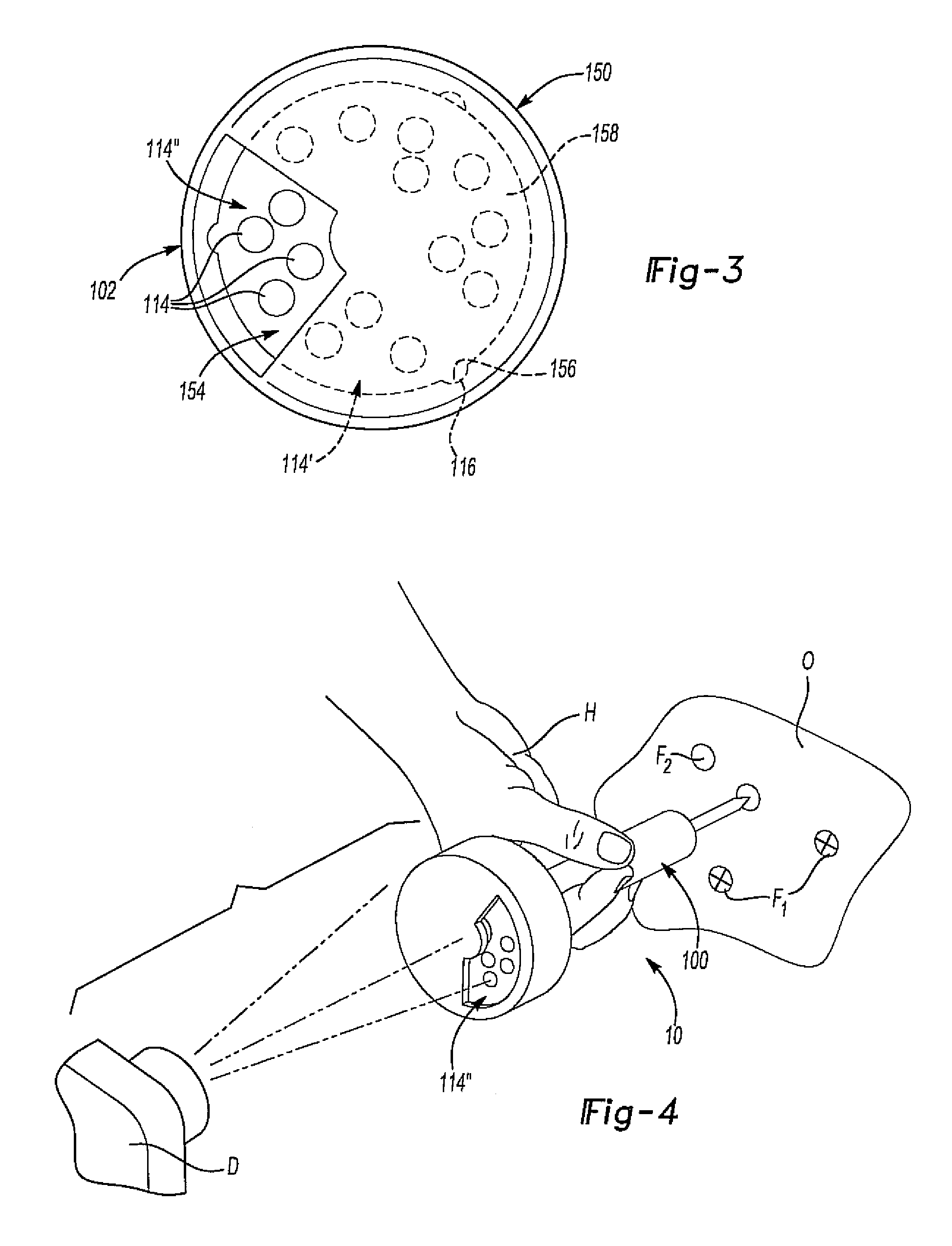
[0015]The present invention provides an adaptive feature recognition tool that can be used to help count and / or locate a plurality of discrete features on an object. Therefore, the present invention has utility as a quality assurance tool.

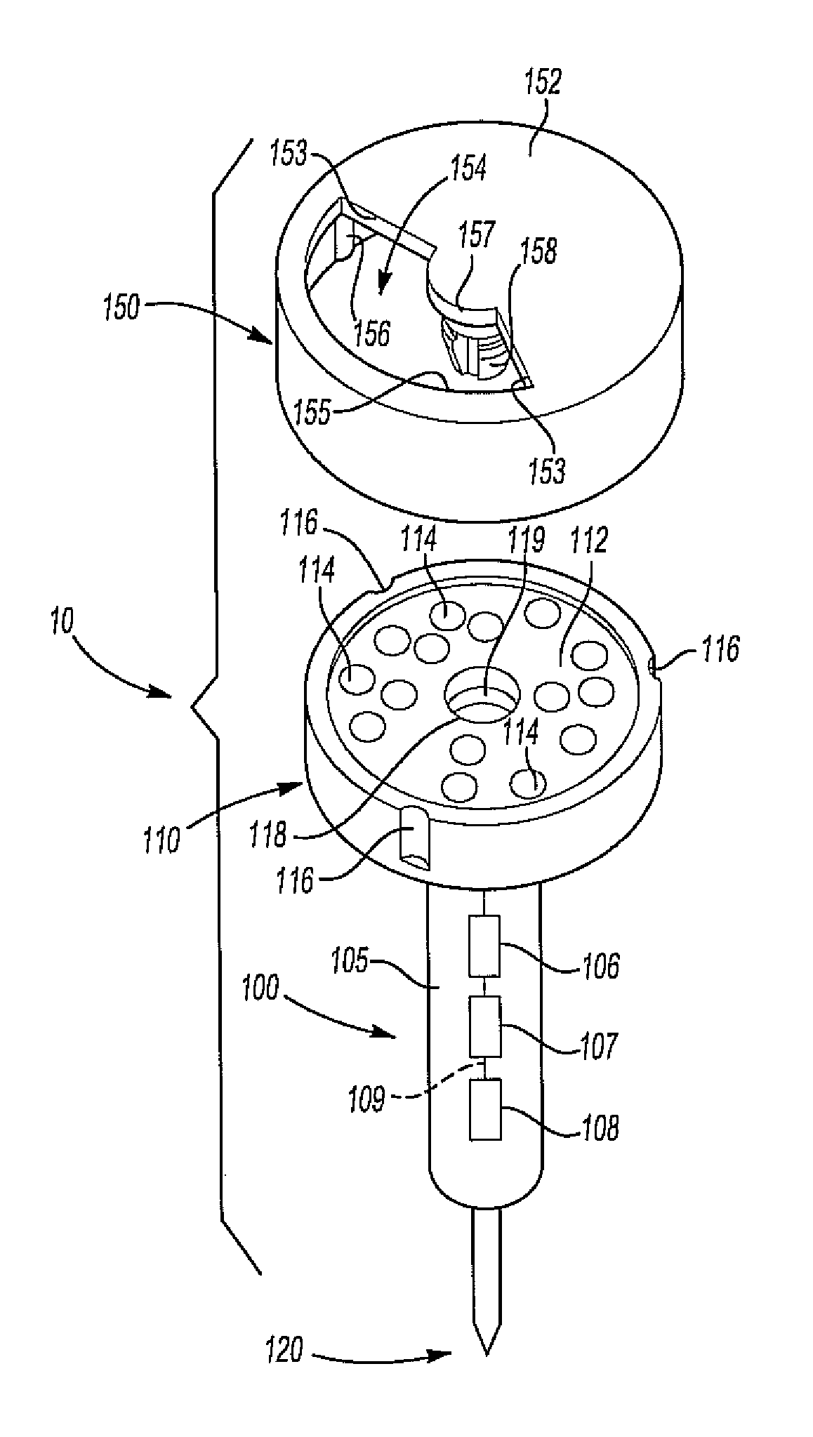
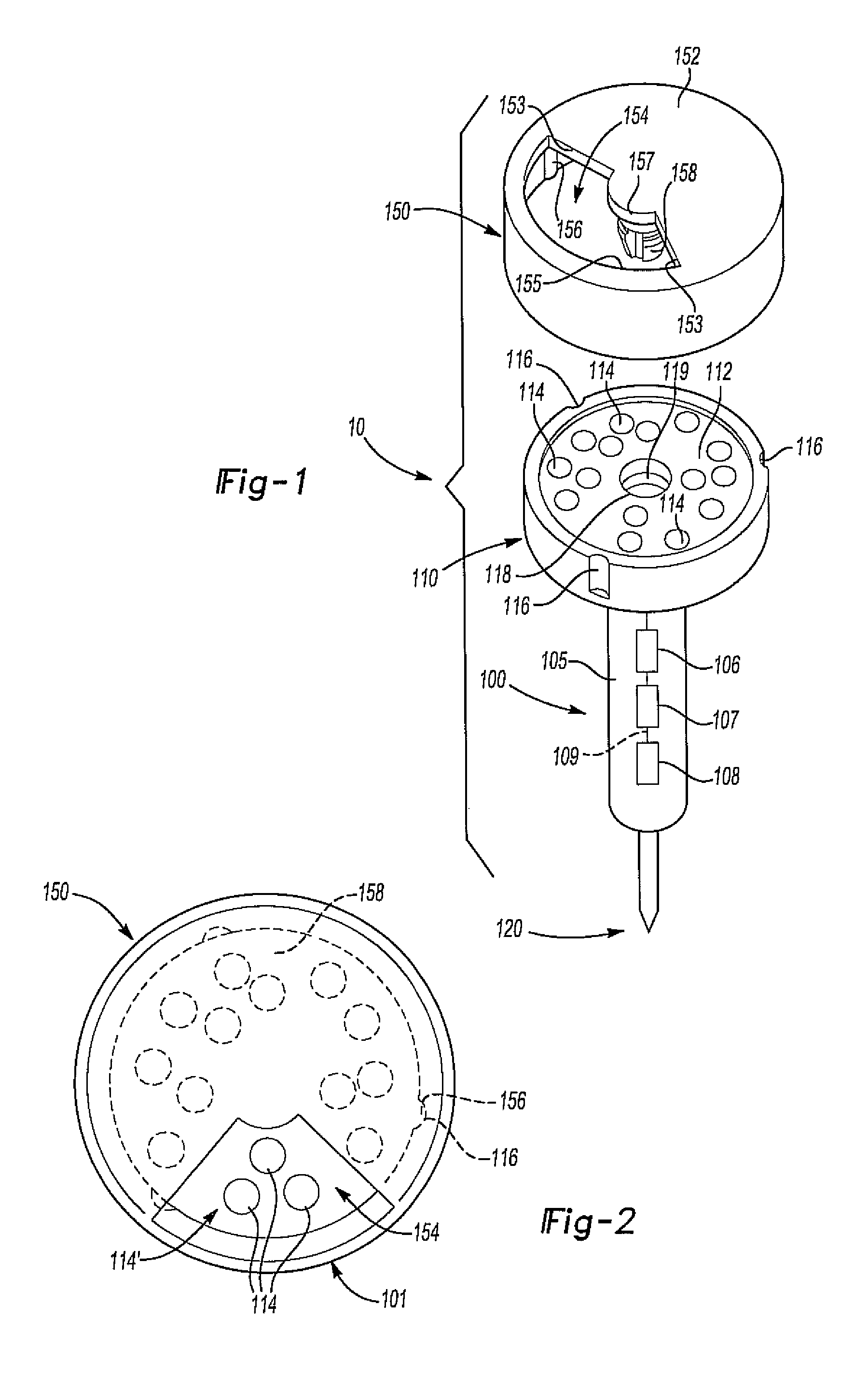
[0016]The adaptive feature recognition tool can be in the form of an elongated rigid member that has a first end with a generally planar surface. In addition, the generally planar surface can have a plurality of contrast targets located thereon. The elongated rigid member can also have a second end that can be placed at a desired location on an object.

[0017]An exposure device, e.g. an adjustable aperture, device that is operable to expose a discrete subset and then one or more subsequent subsets of the plurality of contrast targets to a line-of-sight digital imaging device is also included. In some instances, the exposure device is an opaque cover with an opening that can be attached, e.g. rotatably attached, to the first end of the tool. By placin...


PUM


Abstract

The present invention provides an adaptive feature recognition tool that can be used to determine the location and / or count discrete features on an object being manufactured in a relatively quick time fashion. The tool can include an elongated rigid member that has a first end with a generally planar surface, the generally planar surface having a plurality of contrast targets thereon. The elongated rigid member can also have a second end for placement at a desired location, for example placement on a plurality of features whose number and / or location(s) on the object is desired. In addition, an exposure device that is operable to expose specific subsets of the plurality of contrast targets to a line-of-sight digital imaging device can be included.

Description

FIELD OF THE INVENTION[0001]The present invention is related to a feature recognition tool, and in particular to a single feature recognition tool that can be used to determine the position of and / or count a number of different discrete features on an object.BACKGROUND OF THE INVENTION[0002]An important activity in industrial manufacturing processes is determining the location and / or quantity of various features on an object being manufactured. For example, the location and / or number of specific size or type of holes, studs, welds, and the like on a vehicle frame can be used for quality assurance purposes, modeling, etc.[0003]Heretofore activities for determining the location and / or number of various features include advanced computer-aided photogrammetry in which feature specific attachment position adapters are attached to individual features and / or physically counting of such features. However, the use of heretofor position adapters in combination with advanced computer-aided pho...

Claims


Application Information

Patent Timeline
Patent Type & Authority Patents(United States)
IPC IPC(8): G06K9/00G06T7/00
CPCG06T7/0004G06T2207/30164G06T2207/30242
Inventor DICKINSON, BRIAN RAY
Owner TOYOTA MOTOR ENGINEERING & MANUFACTURING NORTH AMERICA
Why Eureka
Try Eureka