Multi-cell thin film microbattery array

a thin film microbattery array and multi-cell technology, applied in secondary cell manufacturing, final product manufacturing, safety/protection circuits, etc., can solve the problems of microbattery problems, microbattery weaknesses or faults, and particularly difficult manufacture of rechargeable thin film microbatteries on a high yield and high reliability basis, etc., to achieve the effect of extremely low level of inoperability

Active Publication Date: 2016-05-03
CYMBET CORP
View PDF35 Cites 0 Cited by
  • Summary
  • Abstract
  • Description
  • Claims
  • Application Information

AI Technical Summary

Benefits of technology

[0012]It has been found that a single failure that would destroy a single microbattery cell will not destroy functionality of the microbattery cell array of the present invention, because the single failure will only affect one cell, leaving a plurality of cells still operational. Disconnecting the thus identified microbattery cell operates to protect the rest of the microbattery cell array from deep discharge. By providing an array having at least two cells, and preferably at least four cells, a level of redundancy in power supply can be provided so that even if there are multiple failures, the overall microbattery cell construction is still capable of producing operational levels of power. Notably, such failures may occur either in manufacturing, product handling, or in use of the microbattery cell array. The present array therefore provides a corrective feature whereby even if there is a cell failure during the manufacture and supply chain, a functional microbattery cell array product may be provided to the customer at nearly 100% yield. This is a very significant advantage in applications where reliability is of paramount importance. Furthermore, the reliability of the present microbattery cell array is extremely high both at the initial time of supply and over long term use.

Problems solved by technology

Rechargeable thin film microbatteries are in particular difficult to manufacture on a high yield and high reliability basis.
Because of the challenging manufacturing tolerances, weaknesses or faults in thin film microbatteries can be present in the microbattery as initially formed.
Alternatively, a problem could develop in the microbattery during wiring of the microbattery to a device, during initial charge, during use, or even during testing of the viability of the microbattery or attached devices.
In particular, any discontinuities of the electrolyte layer will lead to shorts, and immediate failure of the microbattery.
Additionally, failures of the microbattery may be introduced during routine handling and charge / discharge operations, whereby fractures or dendrite formation may occur that also lead to shorts in the microbattery.
As the footprint size of the microbattery increases, it is increasingly difficult to manufacture and manipulate batteries in an acceptable yield of functioning batteries.
Thus, it is currently not possible to provide microbatteries having a thickness on the order of 50 microns from the respective interior surfaces of the anode to cathode current collectors and having a footprint of 13 cm2 in an acceptable yield.
Because of the nature of use of thin film batteries, failure of a microbattery has catastrophic effects far beyond the value of the microbattery itself.
When the thin film microbattery fails, replacement of the microbattery usually is not a commercially viable option.
The entire microbattery and device combination product is rendered useless, representing a loss of far more than the economic value of the microbattery alone.

Method used


Image

  • Multi-cell thin film microbattery array
  • Multi-cell thin film microbattery array
  • Multi-cell thin film microbattery array

Examples


Embodiment Construction

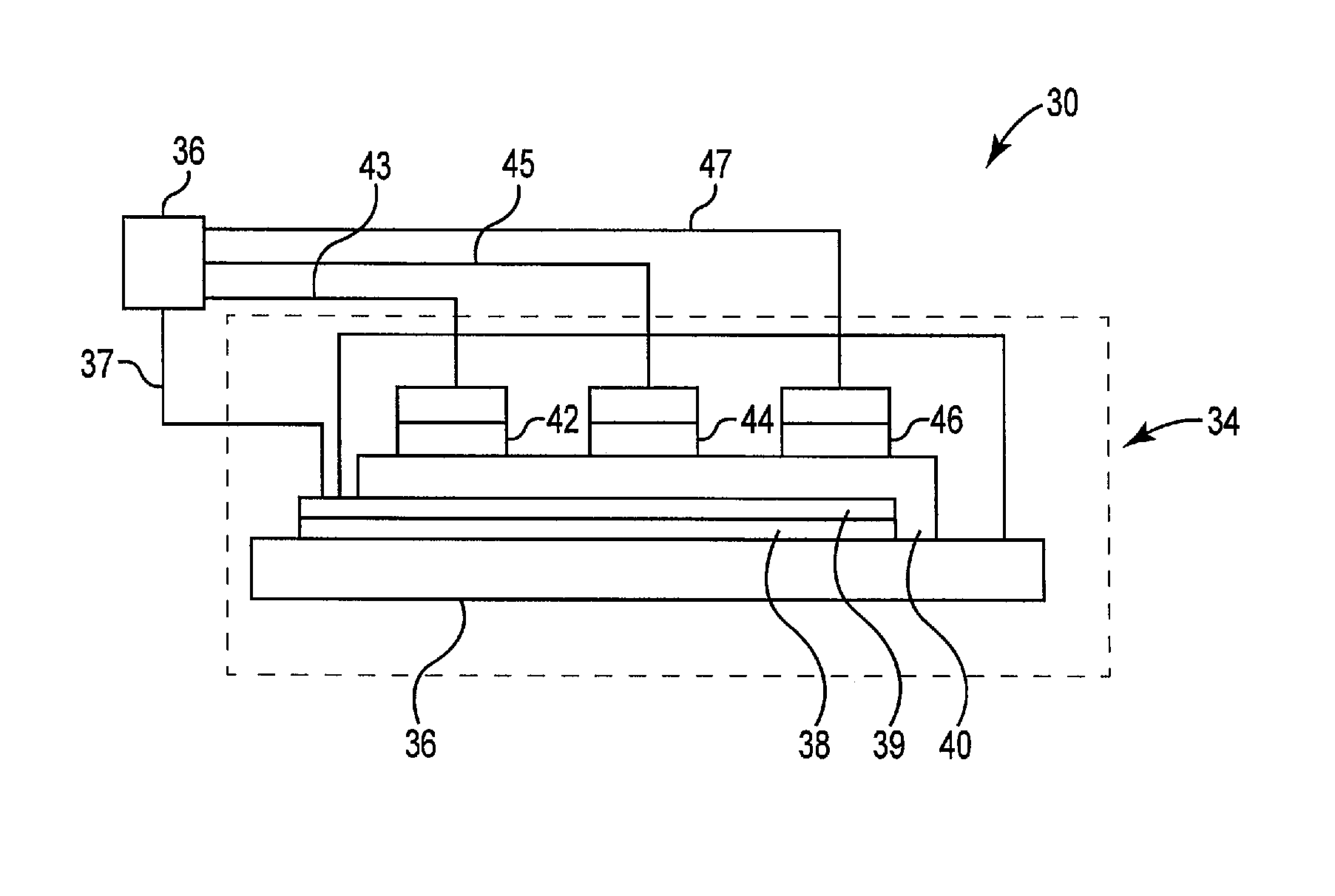
[0026]It is to be understood that a device and method in accordance with the present invention includes, but is not limited to, novel combinations of conventional components, and not just particular detailed configurations thereof. Accordingly, the structure, methods functions, control and arrangement of conventional components and circuits have, for the most part, been illustrated in the drawings by readily understandable block representations and schematic diagrams, in order not to obscure the disclosure with structural details which will be readily apparent to those skilled in the art, having the benefit of the description herein. Further, the invention is not limited to the particular embodiments depicted in the exemplary diagrams, but should be construed in accordance with the language in the claims.

[0027]For purposes of the present invention, a thin film microbattery cell is a microbattery cell having dimensions not exceeding a longest dimension of 60 mm, more preferably not e...


PUM

PropertyMeasurementUnit
areaaaaaaaaaaa
voltage potentialaaaaaaaaaa

Abstract

A rechargeable thin film microbattery cell array of at least four thin film microbattery cells is electrically connected together in parallel to provide power as a single battery power source. The array further comprises testing logic to determine if a microbattery cell has a microbattery cell voltage that is more than a predetermined percentage different from the voltage of the overall microbattery cell array or has an absolute voltage below a predetermined cutoff threshold, and logic to disconnect any microbattery cell from the microbattery cell array if the microbattery cell has a microbattery cell voltage that is more than a predetermined percentage different from the voltage of the overall microbattery cell array or has an absolute voltage below a predetermined cutoff threshold. Embodiments also comprise a Switch Capacitor DC-DC downconverter component that reduces the voltage potential to operate some or all functionalities located on the integrated circuit.

Description

CROSS-REFERENCE TO RELATED APPLICATIONS[0001]This application claims the benefit of U.S. Provisional Application Ser. No. 61 / 524,653, filed Aug. 17, 2011, entitled “MULTI-CELL THIN FILM MICROBATTERY ARRAY” which application is incorporated herein by reference in its entirety.FIELD OF THE INVENTION[0002]This invention relates to the field of thin-film solid-state energy-storage devices, and more specifically to configurations of thin-film solid-state batteries.BACKGROUND OF THE INVENTION[0003]Electronics have been incorporated into many portable devices such as computers, mobile phones, tracking systems, scanners, etc. One drawback to portable devices is the need to include the power supply with the device. Portable devices typically use batteries as power supplies. Batteries must have sufficient capacity to power the device for at least the length of time the device is in use. Sufficient battery capacity can result in a power supply that is quite heavy and / or large compared to the r...

Claims


Application Information

Patent Timeline
Patent Type & Authority Patents(United States)
IPC IPC(8): H01M10/48H02J7/00H01M6/42H01M10/04G01R31/36H01M10/052
CPCH02J7/0021H01M10/0445Y10T307/696H02J7/0026H01M10/0436H01M10/052G01R31/362G01R31/3658G01R31/396G01R31/3835Y02E60/10H02J7/0014H02J7/0048H02J7/00306Y02P70/50H01M10/42H01M10/46H01M10/48H02J7/04
Inventor MULLIN, JEFFREY D.
Owner CYMBET CORP
Why Eureka
Try Eureka