Microwave pulse generator with variable frequency emission

a generator and variable frequency technology, applied in pulse generators, spark gap circuits, pulse techniques, etc., can solve the problems of limiting the frequency bandwidth that can be varied, exposed dipole sections, and prone to dielectric breakdown

Active Publication Date: 2016-05-10
ELECTRONICS & TELECOMM RES INST
View PDF20 Cites 0 Cited by
  • Summary
  • Abstract
  • Description
  • Claims
  • Application Information

AI Technical Summary

Benefits of technology

[0012]Accordingly, the present invention has been made keeping in mind the above problems occurring in the prior art, and an object of the present invention is to provide a high-power microwave pulse generator which has a spark gap switch and an antenna which are designed as a unitary body. The microwave pulse generator can maintain the discharge characteristics of the spark gap, which are relatively constant, while allowing the frequency characteristics of an output pulse to vary within a wide range of at least an octave bandwidth.
[0024]In addition, it is possible to maintain reliable discharge characteristics since the spark gap between the electrode sections stays constant while the depth of the resonance recess is varied.

Problems solved by technology

Unlike the switch section which is operated within high pressure gas, the dipole sections are exposed and are vulnerable to dielectric breakdown with the increasing voltage.
Thus, there is a limit upon generating waveform having frequency-concentrated characteristics in a low frequency band.
In the structure in which high pressure gas is sealed, the gas must be removed, which is inconvenient.
However, the frequency bandwidth that can be varied is very small and the use of this structure is limited.

Method used


Image

  • Microwave pulse generator with variable frequency emission
  • Microwave pulse generator with variable frequency emission
  • Microwave pulse generator with variable frequency emission

Examples


Embodiment Construction

[0032]A reference will now be made in detail to the present invention in conjunction with the accompanying drawings.

[0033]In the description of the present invention, repeated descriptions and detailed descriptions of known functions and components will be omitted when they may make the subject matter of the present invention rather unclear.

[0034]Exemplary embodiments of the invention are provided so that this disclosure will more fully convey the present invention to a person skilled in the art.

[0035]In the drawings, the shapes, dimensions or the like of the components may be exaggerated for the clarity of explanation.

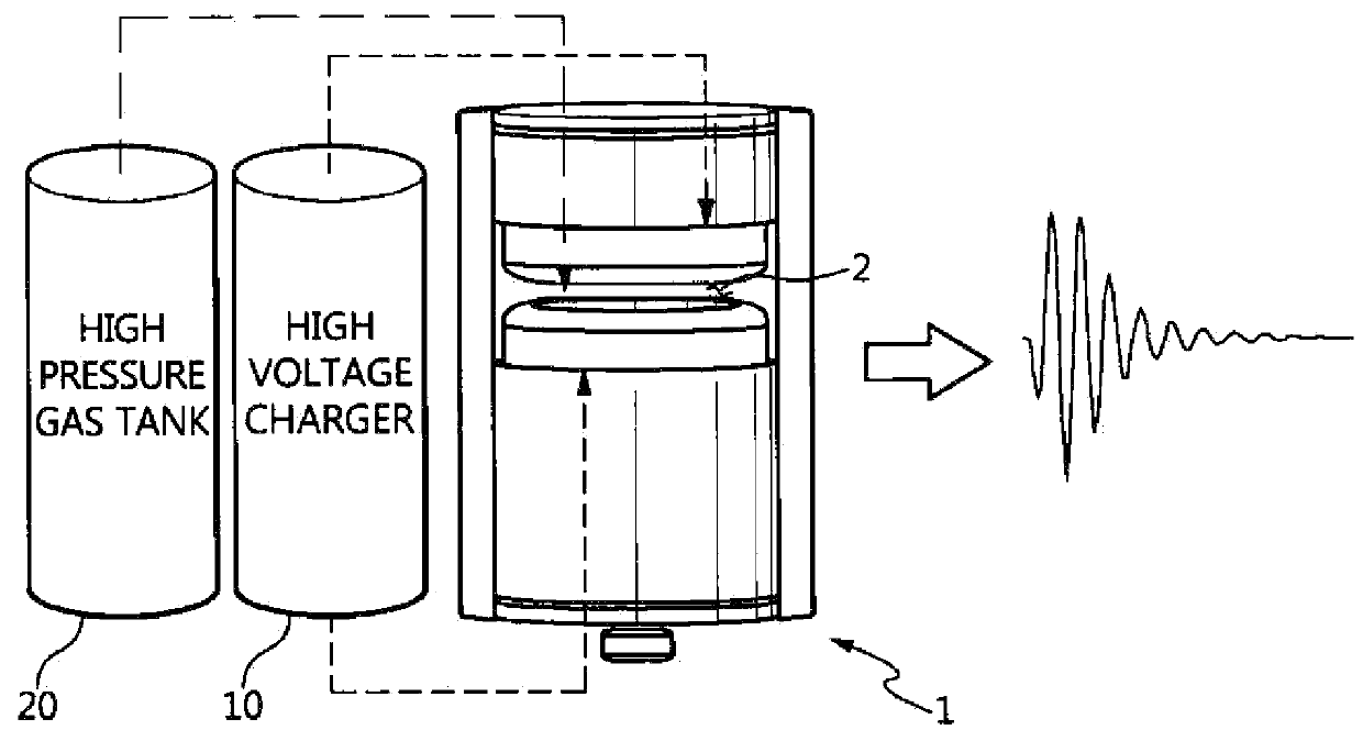
[0036]FIG. 1 is a configuration view showing a variable frequency microwave pulse generator according to the invention.

[0037]With reference to FIG. 1, a description will be given of the variable frequency microwave pulse generator according to the invention with reference. The variable frequency microwave pulse generator includes a high voltage charger 10 for charging...


PUM


Abstract

A variable frequency microwave pulse generator that includes a high voltage charger for charging with a high voltage, a high pressure gas tank for supplying insulation gas, and an electrode discharge unit. The electrode discharge unit includes a case, an accommodation section defined inside the case, and a pair of electrode sections disposed at one side and the other side of the accommodation section so as to face each other. The pair of electrode sections is spaced apart from each other to define a spark gap therebetween where the insulation gas supplied from the high pressure gas tank is loaded. An annular resonance recess is defined at the central portion of one electrode section of the pair of electrode sections, the depth of the resonance recess being variable in response to an adjustment knob disposed on the case being manipulated.

Description

CROSS REFERENCE TO RELATED APPLICATION[0001]This application claims the benefit of Korean Patent Application No. 10-2013-0144794, filed on Nov. 26, 2013, which is hereby incorporated by reference in its entirety into this application.BACKGROUND OF THE INVENTION[0002]1. Technical Field[0003]The present invention relates generally to a microwave pulse generator and, more particularly, to a variable frequency microwave pulse generator which includes a pair of electrodes which define a spark gap in order to generate a strong electromagnetic wave pulse, in which the central frequency of the emitted electromagnetic wave and a resultant output waveform can be adjusted.[0004]2. Description of the Related Art[0005]In general, strong electromagnetic wave pulse generators can be divided into a narrowband device and a wideband device depending on the frequency bandwidths. A narrowband electromagnetic wave pulse is typically generated in response to a high voltage being supplied for several tens...

Claims


Application Information

Patent Timeline
Patent Type & Authority Patents(United States)
IPC IPC(8): H01J7/24H03K3/80H03K3/537
CPCH03K3/80H03K3/537H01T1/22H01T2/02H01T15/00
Inventor LEE, HOONKIM, SUNG-HYUNKIM, SANG-KYUKIM, DONG-MINLEE, KYUNG-HOON
Owner ELECTRONICS & TELECOMM RES INST
Why Eureka
Try Eureka