System and method for performing high-speed communications over fiber optical networks

a fiber optic network and high-speed communication technology, applied in the field of optical fiber communications, can solve the problems of network performance constraint and greater temporal distortion, and achieve the effects of reducing the effect of temporal distortion, increasing data throughput, and increasing reach

Active Publication Date: 2016-05-10
SOTO ALEXANDER I +1
View PDF17 Cites 9 Cited by
  • Summary
  • Abstract
  • Description
  • Claims
  • Application Information

AI Technical Summary

Benefits of technology

[0020]In general, in another aspect, the invention includes a method for communicating data on a fiber optic network, the method including: modulating and demodulating data traffic on an optical link in the network in an m-ary modulation format; encoding and decoding data traffic on an optical link in the network according to an inner coding routine and an outer coding routine, demultiplexing data traffic from an optical link in the network and transmitting the data traffic across a plurality of optical fiber links in the network, multiplexing the data traffic from the plurality of optical fiber links, and equalizing a receive channel in the network to remove temporal distortions.
[0024]Implementations of the invention may include one or more of the following advantages.
[0025]A system is proposed that provides for high-speed communications over fiber optic networks. The system may include the use of the one or more of the following techniques either individually or in combination: m-ary modulation; channel equalization; demultiplexing across multiple fibers, coding and error correction. M-ary modulation allows for increased data throughput for a given line rate due to an increase in the number of bits per symbol transmitted. Channel equalization reduces the effects of temporal distortions allowing for increased reach. Demultiplexing across multiple fibers allows lower lines rates for a given data throughput rate due to the increased aggregate data throughput from the multiplexing. Coding and error correction allows for a greater selection of qualifying optical components that can be used in the network and complements m-ary modulation and channel equalization for overall system performance improvement as measured by transmit energy per bit. These methods when combined (in part or in total) increase the data throughput and reach for fiber optic networks. For PONs in particular, these methods may increase the number of ONU / ONTs and the distance between OLT and ONU / ONT by decreasing the line rate as compared to a conventional communication system of equivalent data throughput.

Problems solved by technology

Temporal distortions are greater, hence a constraint on network performance, with increasing frequency transmission.

Method used


Image

  • System and method for performing high-speed communications over fiber optical networks
  • System and method for performing high-speed communications over fiber optical networks
  • System and method for performing high-speed communications over fiber optical networks

Examples


Embodiment Construction

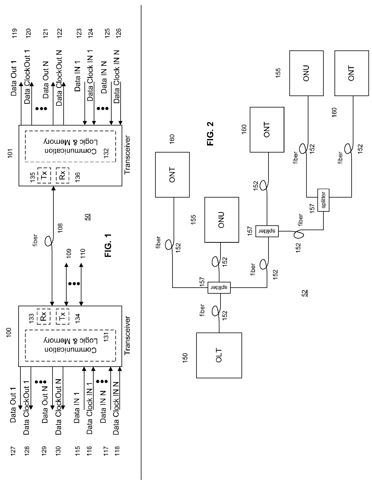
[0037]Referring to FIG. 1, wherein like reference numerals designate identical or corresponding parts throughout the several views and embodiments, a high-level fiber optic data network 50 includes a first transceiver 100 in communication with a second transceiver 101 via a fiber 108. The first transceiver 100 and the second transceiver 101 include transmitter circuitry (Tx) 134, 135 to convert electrical data input signals into modulated light signals for transmission over the fiber 108. In addition, the first transceiver 100 and the second transceiver 101 also include receiver circuitry (Rx) 133, 136 to convert optical signals received via the fiber 108 into electrical signals and to detect and recover encoded data and / or clock signals. First transceiver 100 and second transceiver 101 may contain a micro controller (not shown) and / or other communication logic and memory 131, 132 for network protocol operation. Although the illustrated and described implementations of the transceiv...


PUM


Abstract

Processing a received optical signal in an optical communication network includes equalizing a received optical signal to provide an equalized signal, demodulating the equalized signal according to an m-ary modulation format to provide a demodulated signal, decoding the demodulated signal according to an inner code to provide an inner-decoded signal, and decoding the inner-decoded signal according to an outer code. Other aspects include other features such as equalizing an optical channel including storing channel characteristics for the optical channel associated with a client, loading the stored channel characteristics during a waiting period between bursts on the channel, and equalizing a received burst from the client using the loaded channel characteristics.

Description

CROSS-REFERENCE TO RELATED APPLICATIONS[0001]This application is filed as a 37 C.F.R. 1.53(b)(2) continuation-in-part of the commonly-assigned U.S. patent application Ser. No. 11 / 772,187 filed on Jun. 30, 2007, which claims benefit of commonly-assigned U.S. patent application Ser. No. 10 / 865,547 filed on Jun. 10, 2004, now U.S. Pat. No. 7,242,868, which claims the benefit of U.S. Provisional Application No. 60 / 477,845 filed Jun. 10, 2003, incorporated herein by reference, and U.S. Provisional Application No. 60 / 480,488 filed Jun. 21, 2003, incorporated herein by reference.FIELD OF THE INVENTION[0002]The invention relates to optical fiber communications generally, and more specifically to m-ary modulation in optical communication networks.BACKGROUND OF THE INVENTION[0003]Line coding is a process by which a communication protocol arranges symbols that represent binary data in a particular pattern for transmission. Conventional line coding used in fiber optic communications includes no...

Claims


Application Information

Patent Timeline
Patent Type & Authority Patents(United States)
IPC IPC(8): H04B10/00H04J14/02H04B10/40
CPCH04J14/02H04B10/40H04J14/0256H04J14/0298H04J14/0221H04J14/0227H04J14/0267H04J14/0282H04B10/2507H04B10/2581H04B10/5161
Inventor SOTO, ALEXANDER I.SOTO, WALTER G.
Owner SOTO ALEXANDER I
Why Eureka
Try Eureka