Labeling arrangement for labeling beverage bottles

a beverage bottle and label technology, applied in the field of labeling devices for containers, can solve the problems of adhesive adhesion, corresponding contamination or the need and/or desire for cleaning, maintenance-intensive vacuum systems, etc., and achieve the effect of facilitating release, ensuring maximum adhesion of labels, and facilitating higher adhesion

Inactive Publication Date: 2016-05-17
KHS GMBH
View PDF46 Cites 3 Cited by
  • Summary
  • Abstract
  • Description
  • Claims
  • Application Information

AI Technical Summary

Benefits of technology

[0009]An object of the present application is therefore to make available a device which requires and / or desires less maintenance and at the same time offers increased process security.SUMMARY
[0019]Therefore in one improved configuration, the transport element is formed at least by a base body and one or more carrier elements, whereby the carrier elements can easily be mechanically detached from the base body, and the above mentioned contact surface is located on these carrier elements. For example, the carrier elements can be changed quickly and the overall device can be adapted to the requirements of the transport tasks at hand.
[0021]In the improved variant, the adhesion surface has an adhesion gradient which can be lower in the forward direction of transport of the label, so that it can be released more easily in the first transfer and adhesion area onto a subsequent surface. A variant of this type maybe utilized or adapted for use on a cutting roller, for example. Basically the objective is to achieve the maximum possible adherence of a label, in one possible embodiment on a cutting roller, because the mechanical action of the separating tool can push the label out of the optimal position or fold or wrinkle it. A maximum adhesive adherence, however, interferes with the transfer to a subsequent transport element. Therefore the variant comprises shaping the surfaces to the left and right of the cutting line so that they have different adhesive forces. Therefore when the device is operating properly, ideally the rear end of the label to be separated is fixed in position with the maximum possible adhesion force onto the cutting roller, whereby the subsequent, uncut label which forms the end of the strip is held in the area adjacent to the cutting edge with a slightly lower adhesion force.
[0022]This part of the label, which sticks to the surface in the area of lower adhesion, for the remainder of the process is first transferred to a subsequent transport element or container. The transfer to a transport element with higher adhesion is thereby made easier.

Problems solved by technology

Vacuum systems are also maintenance-intensive and as a result of the air intake, particles of dirt are sucked in and get into the vicinity of the labeling systems, which results in corresponding contamination or the need and / or desire for cleaning.
A maximum adhesive adherence, however, interferes with the transfer to a subsequent transport element.

Method used


Image

  • Labeling arrangement for labeling beverage bottles
  • Labeling arrangement for labeling beverage bottles
  • Labeling arrangement for labeling beverage bottles

Examples


Embodiment Construction

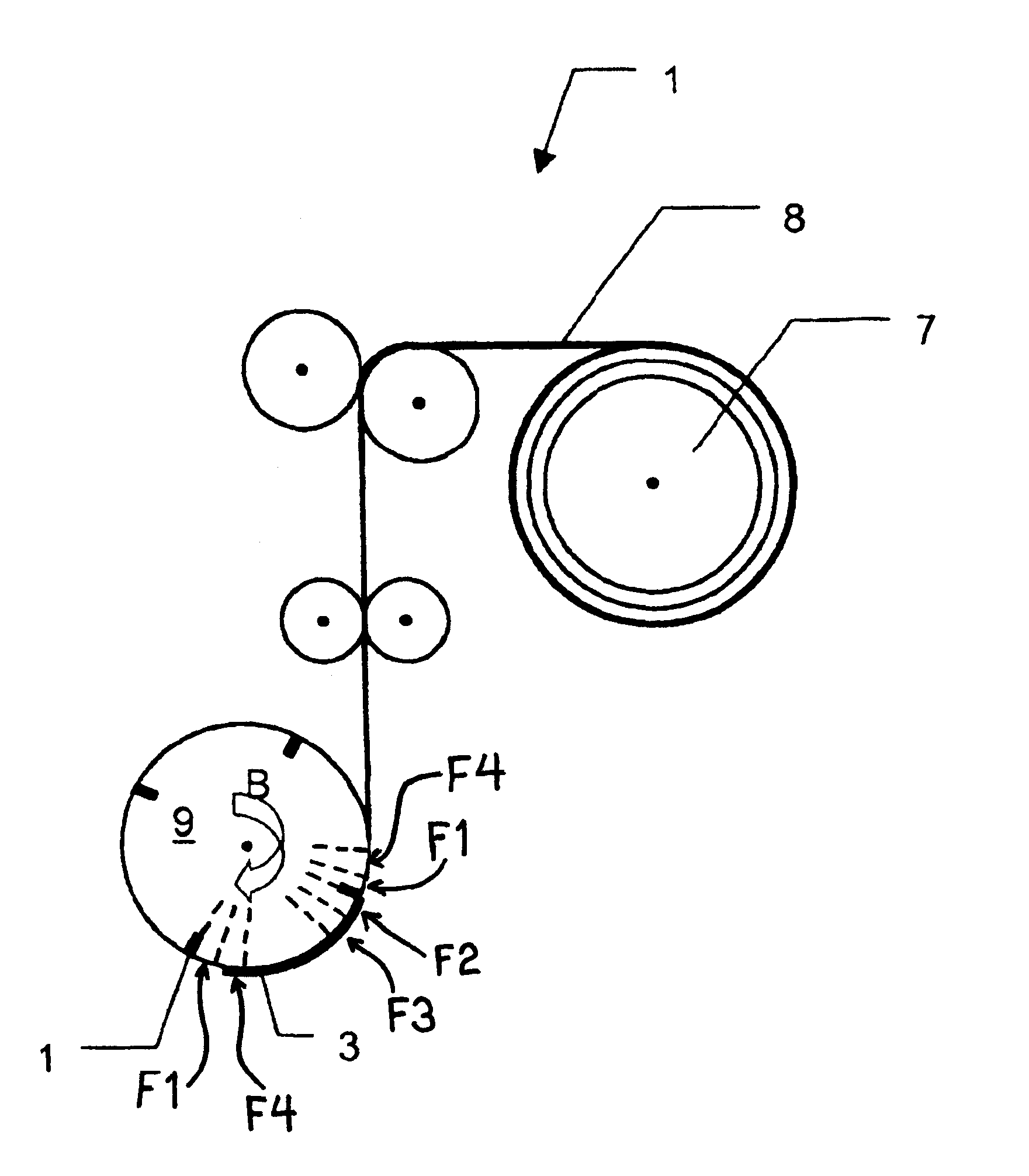
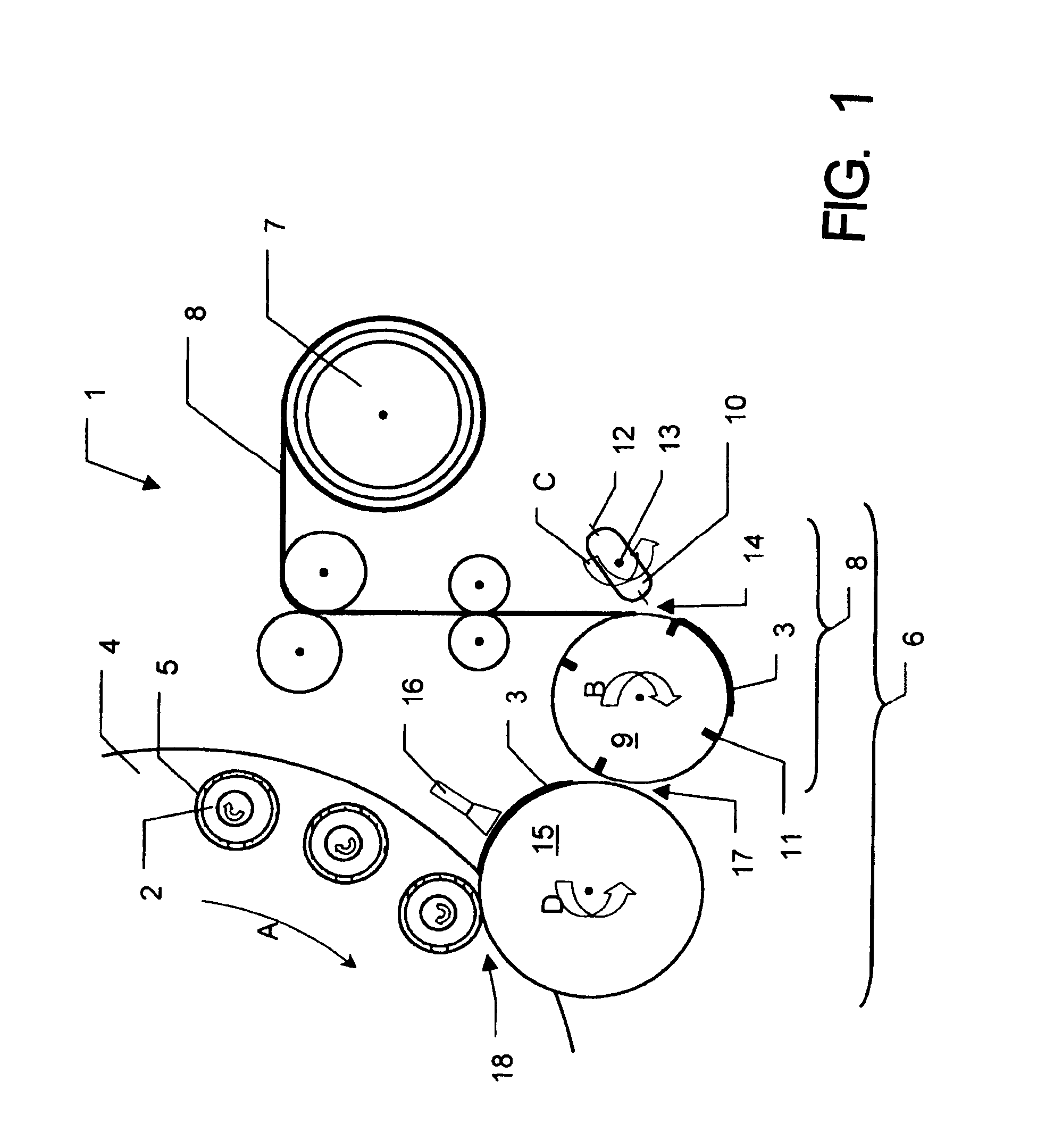
[0049]The labeling machine that employs a rotary construction and is designated 1 in general in FIG. 1 is used for the labeling of containers 2 which are realized in the form of bottles with labels 3, and in one possible embodiment in the illustrated embodiment with all-around or wrap-around labels.

[0050]The labeling machine 1, in a manner that will be familiar to a technician skilled in the art, comprises among other things a rotor 4 which is driven in rotation around a vertical machine axis in the direction indicated by the Arrow A. On the periphery of the rotor 4 there are a plurality of container carriers 5 in the form of turntables, on each of which, during the labeling operation, one container 2 is held in the upright position, i.e. with its container axis in the vertical direction oriented parallel or substantially parallel to the machine axis. The containers 2 to be labeled are fed to the labeling machine 1 or to the rotor 4 at a container inlet (not shown). The containers 2...


PUM

PropertyMeasurementUnit
distanceaaaaaaaaaa
distanceaaaaaaaaaa
distanceaaaaaaaaaa

Abstract

A labeling arrangement for labeling beverage bottles. The abstract of the disclosure is submitted herewith as required by 37 C.F.R. §1.72(b). As stated in 37 C.F.R. §1.72(b): A brief abstract of the technical disclosure in the specification must commence on a separate sheet, preferably following the claims, under the heading “Abstract of the Disclosure.” The purpose of the abstract is to enable the Patent and Trademark Office and the public generally to determine quickly from a cursory inspection the nature and gist of the technical disclosure. The abstract shall not be used for interpreting the scope of the claims. Therefore, any statements made relating to the abstract are not intended to limit the claims in any manner and should not be interpreted as limiting the claims in any manner.

Description

CONTINUING APPLICATION DATA[0001]This application is a Continuation-In-Part application of International Patent Application No. PCT / EP2007 / 009792, filed on Nov. 13, 2007, which claims priority from Federal Republic of Germany Patent Application No. 10 2007 009 152.6, filed on Feb. 24, 2007. International Patent Application No. PCT / EP2007 / 009792 was pending as of the filing date of this application. The United States was an elected state in International Patent Application No. PCT / EP2007 / 009792.BACKGROUND[0002]1. Technical Field[0003]The present application relates to a labeling device for containers in which the transport elements have one or more structured contact surfaces with elevated adhesion, and the labels are held exclusively by adhesion forces. The structured surface is thereby formed by a plurality of projections which have a base section and a top section, whereby the top section has an end surface which is directed away from the surface, whereby each projection is of a s...

Claims


Application Information

Patent Timeline
Patent Type & Authority Patents(United States)
IPC IPC(8): B29C65/56B65C9/18B65C9/12B65C9/36B30B15/00B32B37/26B32B37/10B32B37/14B32B37/22B32B38/14B32B38/18
CPCB65C9/12B65C9/1803B65C9/36Y10T156/12Y10T156/1744Y10T156/10
Inventor TILL, VOLKER
Owner KHS GMBH
Why Eureka
Try Eureka