Electrically conductive pipette tip

a technology tip, which is applied in the field can solve the problems of reducing the safety of use, the difficulty of visual inspection of users during use, and the cost of electrically conductive pipette tip is comparatively high, so as to prevent the problem of stress distribution and distortion of the pipette tip, avoid excessive flow resistance, and promote the effect of secure contact of the syring

Active Publication Date: 2016-05-24
EPPENDORF SE
View PDF18 Cites 40 Cited by
  • Summary
  • Abstract
  • Description
  • Claims
  • Application Information

AI Technical Summary

Benefits of technology

[0019]The conductivity of the pipette tip according to the invention is ensured in that its body has at least one continuous, electrically-conductive region consisting of a first plastic component extending in the lengthwise direction of the tubular body. Consequently, an electrical current can flow from the immersed, bottom end to the top end of the electrically-conductive region of the pipette tip that can be connected to a pipette. In addition, the pipette tip has at least one region consisting of a transparent, second plastic component that extends from the passageway to the outside of the body. This allows the user to visually check whether or not the pipette tip is filled with liquid. If necessary, the level can be visually inspected. In addition, the pipette tip according to the invention can be manufactured more economically than conventional electrically conductive pipette tips since it has at least one transparent region consisting of plastic that can be designed without electrically conductive material.
[0032]According to one embodiment, the molded body is exposed at least at the bottom opening and top opening of the body. This ensures that the molded body is wet by a liquid in which the pipette tip is immersed and contacts a pipette that is releasably connected to the pipette tip. According to another embodiment, the molded body between the bottom opening and top opening is completely or partially embedded in the transparent plastic of the body. This allows the molded body to be firmly connected to the pipette tip.
[0035]According to another embodiment, the electrically conductive strip is at least 1 mm wide. This is particularly advantageous in the production of tips using a two-component injection molding process since excessive flow resistance is avoided.
[0036]According to one embodiment, a plurality of sections of the electrically-conductive regions, or printings, or a plurality of molded bodies are evenly distributed over the perimeter of the body. This can prevent the problematic distribution of stress and distortion of the pipette tip during injection molding. This is particularly advantageous for manufacturing in a two-component injection molding process, but also for printing and molding on or overmolding a molded body.
[0037]According to another embodiment, the pipette tip has strip-shaped sections of the electrically-conductive region, or printings, or molded bodies on at least two diametrically opposing sides of the body. In particular, this promotes the secure contacting of the syringe by the pipette.
[0039]According to another embodiment, the electrically-conductive region, or printings, or molded body have at least one ring and / or ring segment that extends in the peripheral direction of the body. By means of the ring and / or the ring segment, sections of the electrically-conductive region spaced from each other in a peripheral direction, or printings spaced from each other, or molded bodies spaced from each other can be connected to each other in an electrically conductive manner. In addition, the contacting of the liquid and / or contact with a dosing device can be ensured depending on the alignment of the pipette tip by means of the ring and / or ring segment. According to another embodiment, a ring and / or ring segment extends around the bottom end and / or around the top end of the pipette tip. The ring and / or ring segment can however also extend at a distance from the bottom end and / or top end of the pipette tip.

Problems solved by technology

Therefore the user cannot visually check during use if the pipette tip contains liquid or not.
In addition, the cost of electrically conductive pipette tips is comparatively high since a carbon black component has to be processed.

Method used


Image

  • Electrically conductive pipette tip
  • Electrically conductive pipette tip
  • Electrically conductive pipette tip

Examples


Embodiment Construction

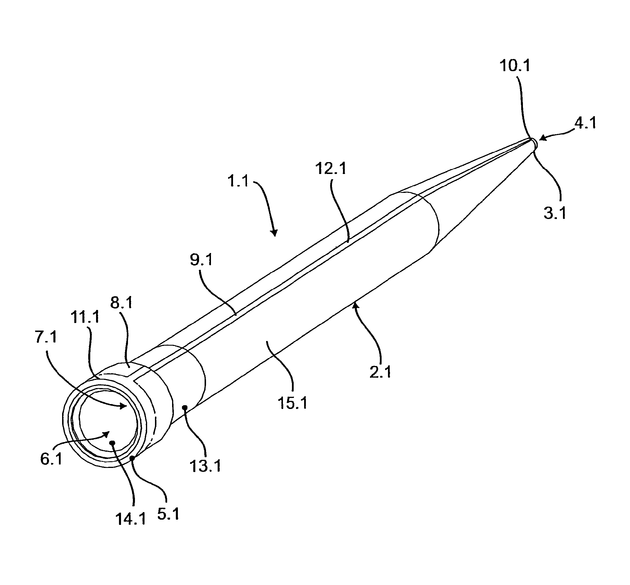
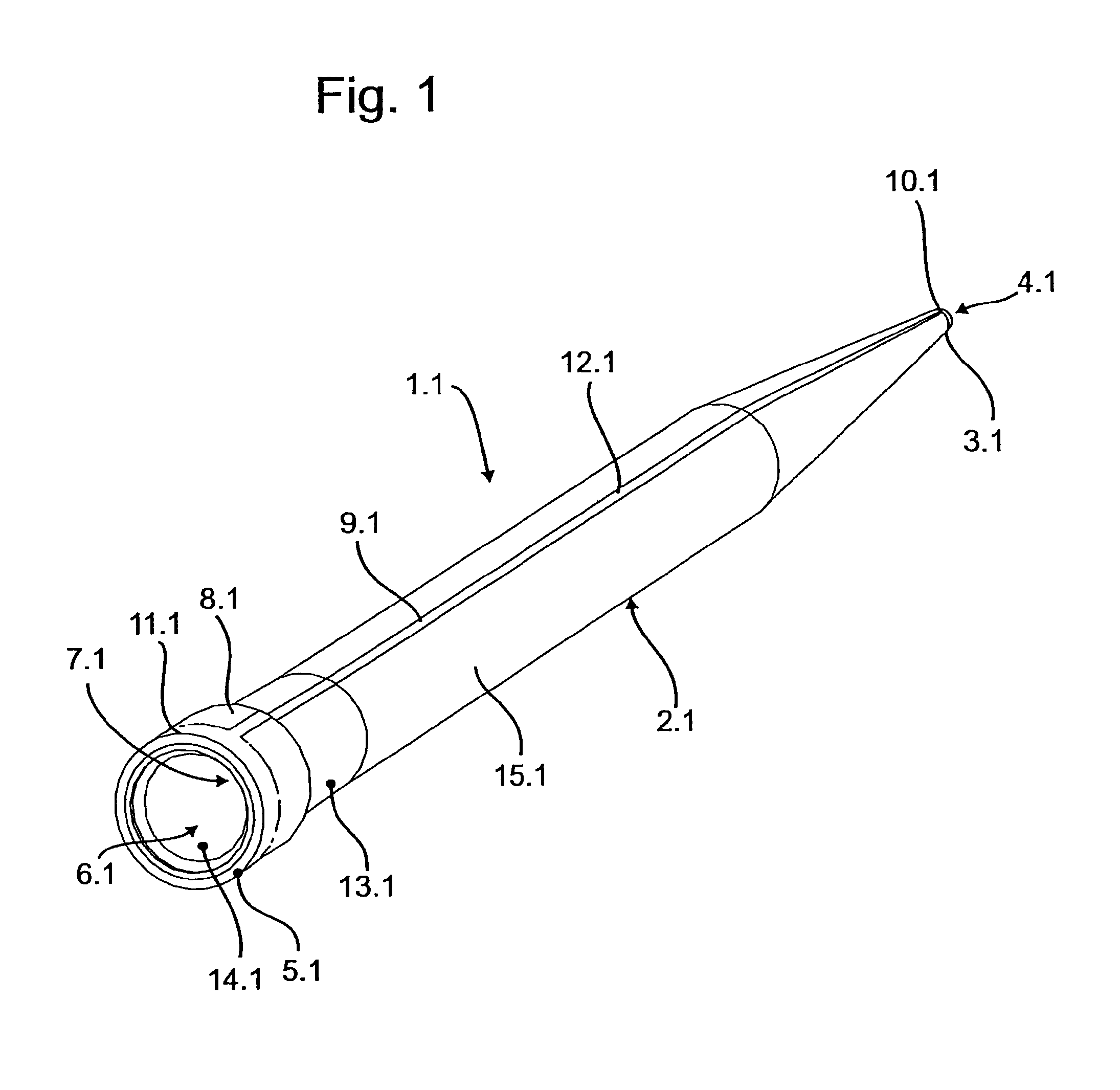
[0052]While this invention may be embodied in many different forms, there are described in detail herein a specific preferred embodiment of the invention. This description is an exemplification of the principles of the invention and is not intended to limit the invention to the particular embodiment illustrated.

[0053]In the present application, the terms “top” and “bottom” refer to the preferred alignment of the pipette tip during use in which the pipette tip with its body is vertically aligned, and the bottom opening is arranged at the bottom, and the top opening is arranged at the top.

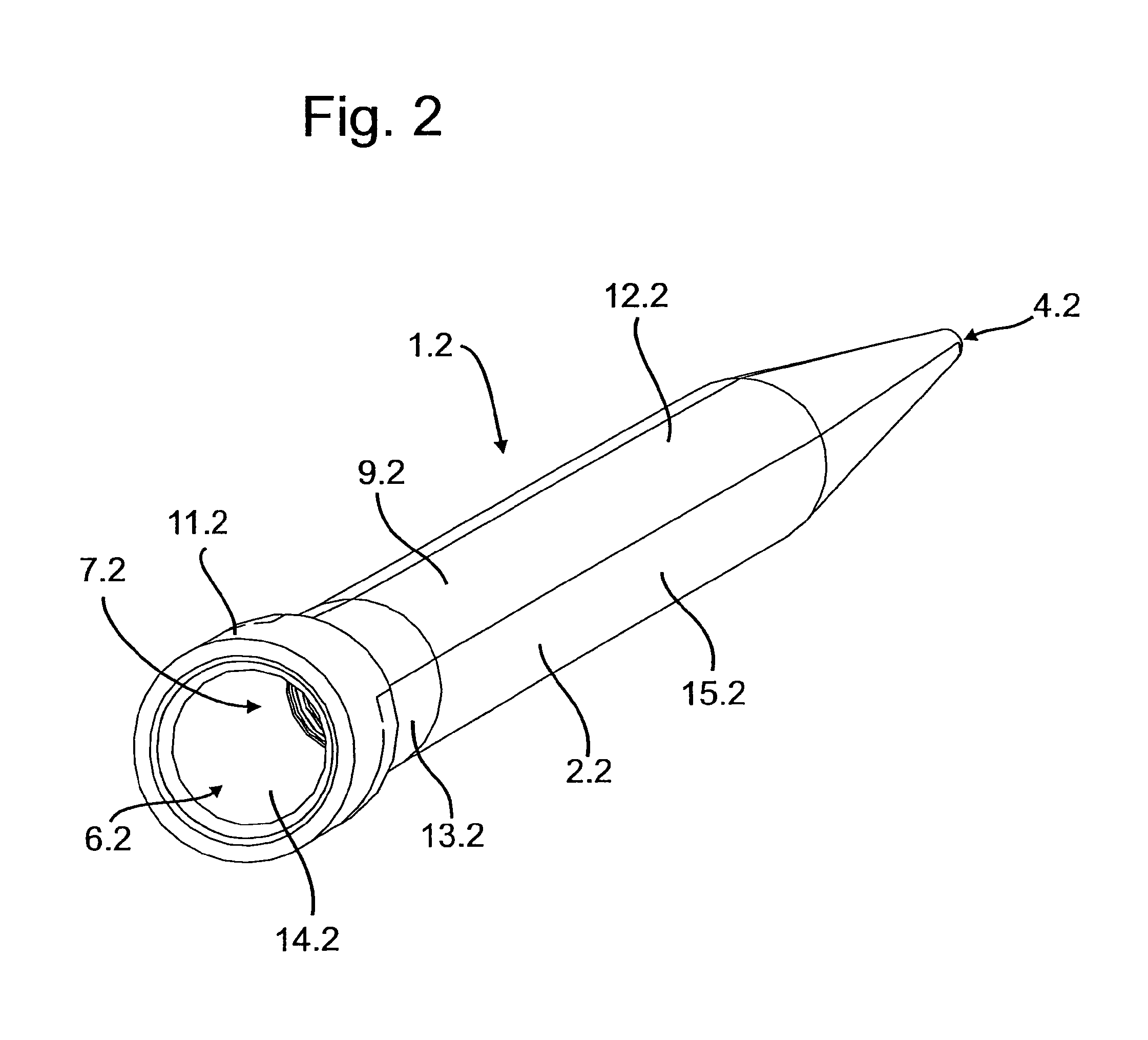
[0054]In the following explanation of various exemplary embodiments, the parts identified with the same terms are provided with the same reference numbers, the various exemplary embodiments differing from each other by a subsequent period and different numbers after the period.

[0055]According to FIG. 1, a pipette tip 1.1 manufactured in a two-component injection molding process has a tubular body 2.1...


PUM


Abstract

An electrically conductive pipette tip having an elongated tubular body that has a bottom opening at the bottom end for the passage of liquid, and a top opening at the top end for the passage of air, and a passageway between the bottom opening and the top opening, wherein the body has at least one electrically-conductive region extending from the bottom opening to the top opening, and at least one transparent region consisting of plastic that extends from the passageway to the outside of the body.

Description

CROSS-REFERENCE TO RELATED APPLICATIONS[0001]Not applicableSTATEMENT REGARDING FEDERALLY SPONSORED RESEARCH[0002]Not applicableBACKGROUND OF THE INVENTION[0003]The invention relates to an electrically conductive pipette tip.[0004]Pipette tips are used together with pipettes for dosing liquids. Pipette tips have an elongated tubular body having a bottom opening at the bottom end for the passage of fluid, and a top opening at the top end for the passage of air, and a passageway between the bottom opening and top opening. Pipette tips are releasably connected to a pipette. To accomplish this, the top opening is conventionally clamped to a mounting shaft at the bottom end of the pipette, or the top end is clamped in a blind hole in the bottom end of the pipette. The bottom end of the mounting shaft, or the blind hole in the top end, has a passage for air that is connected via a connecting channel to a displacement unit for air. The displacement unit is generally designed as a piston / cyl...

Claims


Application Information

Patent Timeline
Patent Type & Authority Patents(United States)
IPC IPC(8): B01L3/02G01F23/02G01F23/26
CPCB01L3/021B01L3/0275G01F23/02G01F23/268B01L2300/0645B01L2300/0858B01L2300/168
Inventor BLUMENTRITT, MICHAELGULZOW, NICOREIMANN, THOMASZIEGMANN, CHRISTIANHAAK, MATTHIAS
Owner EPPENDORF SE
Why Eureka
Try Eureka