Microchip

a microchip and chip technology, applied in the field of microchips, can solve the problems of liquid moving in an unintended direction, and achieve the effects of preventing fluctuation of test or analysis results attributed to a kind of sample, high reliability of test or analysis results, and accurate measuremen

Inactive Publication Date: 2016-05-24
HORIBA LTD
View PDF8 Cites 0 Cited by
  • Summary
  • Abstract
  • Description
  • Claims
  • Application Information

AI Technical Summary

Benefits of technology

[0019]The present invention was achieved in view of the problems described above, and its object is to provide a microchip capable of preventing movement of the liquid in the fluid circuit in an unintended direction due to wettability of the liquid with respect to an inner surface of the fluid circuit, such as the reverse flow phenomenon to assuredly perform a desirable fluid treatment as designed, and thereby reproducibly obtaining reliable test or analysis result.
[0020]Further, another object of the present invention is to provide a microchip capable of preventing fluctuation in test results due to difference in kinds of samples to exhibit improved test or analysis accuracy.
[0068]According to the present invention, the recess is provided, so that movement of liquid in the fluid circuit in an unintended direction, as exemplified by the reverse flow phenomenon described above, can be prevented, and fluid treatment as intended by design can be assuredly performed. Thus, according to the present invention, a microchip capable of reproducibly obtaining highly reliable test or analysis result can be provided.
[0069]Further, according to the microchip of the present invention, unintended flowing out of measured liquid in the measuring portion based on tensional force due to wettability can be prevented regardless of a kind of a sample. Therefore, accurate measurement can be performed regardless of a kind of a sample. Thus, according to the microchip of the present invention, fluctuation of test or analysis result attributed to a kind of a sample can be prevented, and test or analysis accuracy can also be improved.

Problems solved by technology

However, in the fluid treatments, liquid sometimes moved in an unintended direction that is different from the direction of applying the centrifugal force due to wettability of the liquid with respect to an inner surface of the fluid circuit.

Method used


Image

  • Microchip
  • Microchip
  • Microchip

Examples


first embodiment

(1) First Embodiment

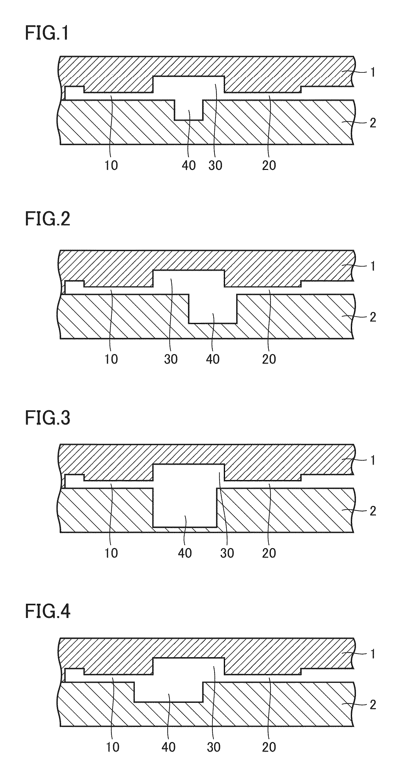
[0117]FIG. 1 is a cross-sectional view schematically representing one example of a microchip according to the present embodiment. The microchip shown in FIG. 1 is composed of a first substrate 1, which is a transparent substrate, and a second substrate 2 stacked on and laminated with first substrate 1. A surface of first substrate 1 on a side facing second substrate 2 is provided with a plurality of grooves forming a fluid circuit, and the plurality of grooves include a first groove 10 forming a first space, a second groove 20 forming a second space, and a third groove 30 coupling first groove 10 with second groove 20 (laying between first groove 10 and second groove 20). This third groove 30 is a groove forming a space connecting portion.

[0118]First groove 10, second groove 20, and third groove 30 are aligned approximately linearly. Although not explicitly shown in FIG. 1, a base area of third groove 30 is larger than base areas of first groove 10 and second gro...

second embodiment

(2) Second Embodiment

[0138]FIGS. 7 and 8 are cross-sectional views schematically representing examples of the microchips according to the present embodiment. The microchips shown in FIGS. 7 and 8 basically have the same structure as that of the microchip according to the first embodiment other than that a protrusion 45 protruding from a side wall surface of recess 40 on a side of first groove 10 and having such a protrusion length of not allowing an end portion thereof to be in contact with a side wall surface (a side wall surface on a side of second groove 20). The difference between the microchips of FIG. 7 and the microchip of FIG. 8 is whether or not a cavity portion is formed directly under protrusion 45 depending on a manufacturing method of second substrate 2. The structure of the fluid circuit and the function of recess 40 are the same for both microchips. The microchips shown in FIGS. 7 and 8 are improved embodiments of the microchip shown in FIG. 1, and providing protrusio...

third embodiment

(1) Third Embodiment

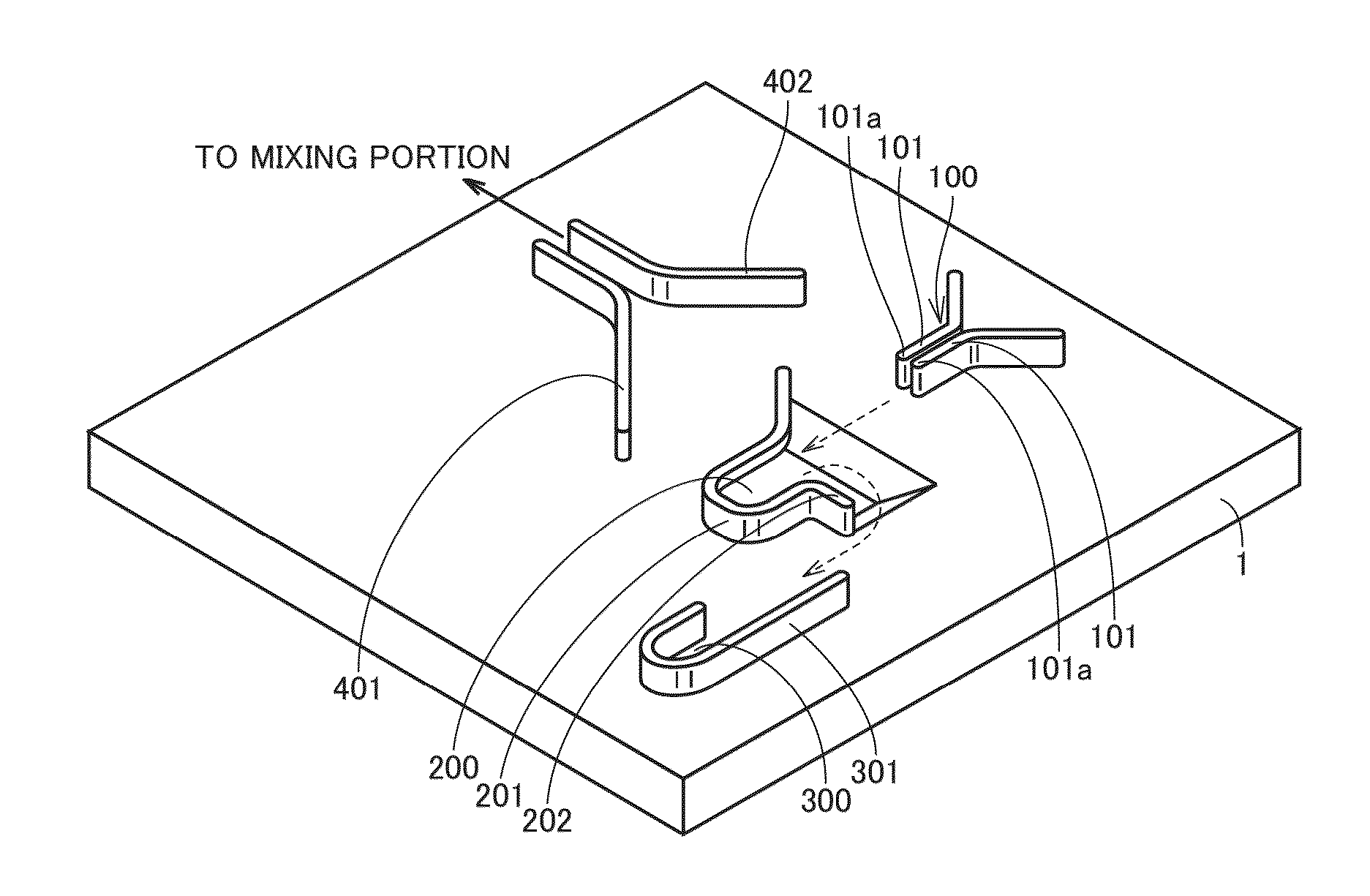
[0152]FIG. 12 is a perspective view schematically representing one example of characterizing portions (measuring portion, liquid introducing portion, overflow liquid storage, and peripheral portion) of the fluid circuit of the microchip according to the present embodiment. The microchip shown in FIG. 12 is composed of first substrate 1, which is a transparent substrate, and a second substrate, which is an opaque substrate, stacked on and laminated with the surface on which the groove is formed. For clear understanding as to the configuration of the groove of first substrate 1 forming the characterizing portions of the fluid circuit, the second substrate is omitted in FIG. 12 (this applies similarly to FIGS. 13 and 17).

[0153]In the microchip shown in FIG. 12, the fluid circuit includes flow paths composed of: a liquid introducing portion 100 which is a flow rate restricting portion composed of a space (second space) partitioned by a pair of side walls 101, 101 (se...


PUM


Abstract

A microchip including a fluid circuit composed of a space formed inside is provided. The space includes a first space, a second space, and a space connecting portion connecting the first space and the second space, and the space connecting portion has a structure portion restraining liquid moving between the first space and the second space from moving due to wettability with respect to the space connecting portion surface.

Description

BACKGROUND OF THE INVENTION[0001]1. Field of the Invention[0002]The present invention relates to a microchip having an internal fluid circuit therein suitably used for biochemical test, chemical synthesis, environmental analysis, and the like.[0003]2. Description of the Background Art[0004]In recent years, in the fields of medical care, health, food, drug discovery, and the like, detection or quantitation of biological substances such as DNA, enzyme, antigen, antibody, protein, virus, or cell as well as chemical substances has become increasingly important, and various biochips and micro chemical chips (such chips will hereinafter be collectively referred to as “microchip”) with which the above-described substances can be easily and conveniently measured have been proposed.[0005]The microchip can be used to allow a series of experimental and analytical operations, which are conventionally performed in a laboratory, to be conducted within the small chip. The microchip accordingly pro...

Claims


Application Information

Patent Timeline
Patent Type & Authority Patents(United States)
IPC IPC(8): B01L3/00
CPCB01L3/502753B01L3/502738B01L3/502746B01L2200/0621B01L2300/087B01L2300/0816B01L2300/0864B01L2300/0867B01L2400/0406B01L2400/0409B01L2400/0688B01L2400/086B01L2400/088
Inventor MOMOSE, SHUN
Owner HORIBA LTD
Why Eureka
Try Eureka