Chassis for electric vehicle

a technology for electric vehicles and chassis, applied in the field of chassis, can solve the problems of affecting the design of electric vehicles, affecting the economic viability of electric vehicles, and carries a substantial weight penalty, and achieves the effects of low density, low cost and high rigidity

Active Publication Date: 2016-05-24
GORDON MURRAY TECH LTD
View PDF11 Cites 23 Cited by
  • Summary
  • Abstract
  • Description
  • Claims
  • Application Information

AI Technical Summary

Benefits of technology

[0007]The aligned fibres can extend from one fixing point to another fixing point, allowing load transfer within the combined structure that is the chassis element and the remainder of the chassis. This enables the battery casing to form part of the loadbearing structure of the chassis, reducing the overall weight of the vehicle and improving its performance. At the same time, making the battery case part of the chassis allows it to be made accessible; the vehicle's chassis element can (for example) be accessed from beneath the vehicle, released from the remainder of the chassis and lowered out of the vehicle. It can then be replaced with a unit carrying fresh batteries, or opened to allow replacement of the batteries within it.
[0008]In this way, the invention allows the design of a removable section of the chassis that, when fitted, forms an integral part of the loadbearing design of the chassis, but which can be removed straightforwardly to allow for replacement of the batteries. Compared to the existing approach of simply placing the batteries somewhere within a complete chassis, significant weight can be saved and access to the batteries can be significantly improved.
[0011]The core material is preferably less dense than the skin material, thereby allowing the composite element to have a light weight and a high rigidity.
[0012]In an embodiment, one part of the outer skin material extends in a planar manner from one fixing point to another. For example, where the outer skin material has first and second parts on either side of the inner core material, the first part may extend in a planar manner between the plurality of fixing points. The flat part of the skin lends the sheet a high degree of rigidity and allows it to bear loads once connected as part of a chassis. It also lends the chassis an improved aerodynamic drag than might otherwise be the case.

Problems solved by technology

The Toyota Prius hybrid integrates the batteries into the vehicle more effectively, with the result that their replacement is regarded by some as not economically viable, implying a service life for the vehicle of only 150,000 km (approx 100,000 miles).
This approach hampers the design of electric vehicles.
The inherited chassis is usually of a pressed steel construction, which carries a substantial weight penalty.
Often, the batteries are located behind the passengers and would therefore inflict serious injuries if unrestrained during a frontal collision.
Such an enclosure or restraint is usually of steel or other similar construction, adding still further weight.
Designing this in a way that allows for easy replacement of the batteries will add further complexity and weight.

Method used


Image

  • Chassis for electric vehicle
  • Chassis for electric vehicle
  • Chassis for electric vehicle

Examples


Embodiment Construction

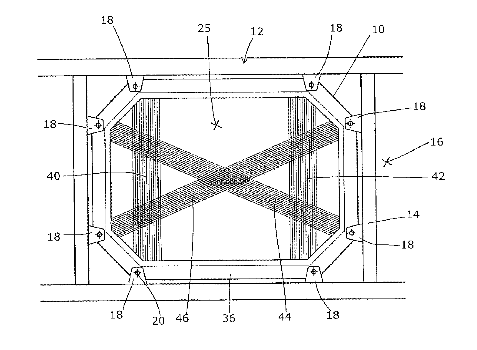
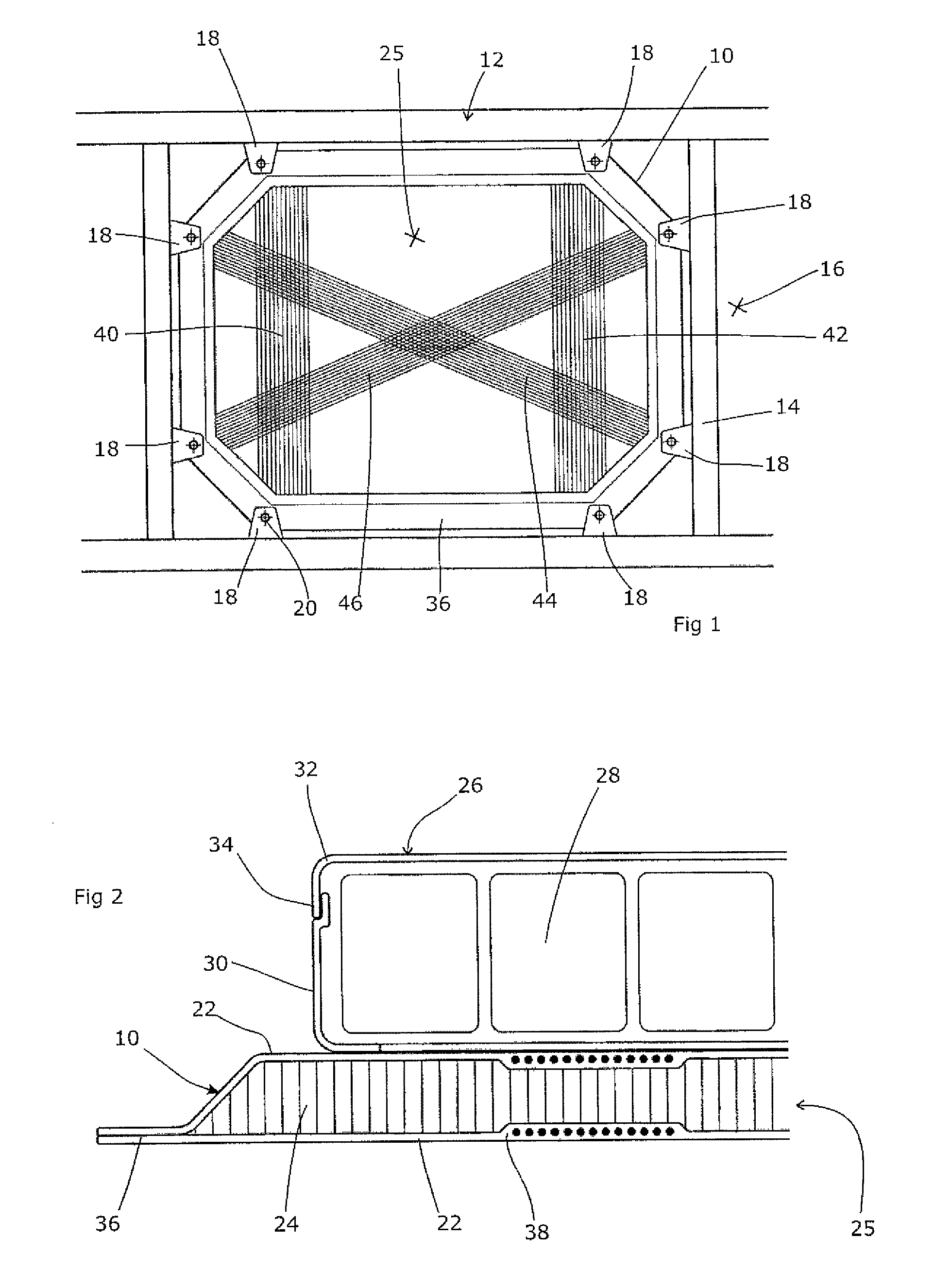
[0020]FIG. 1 shows the chassis element 10 of the present invention, fitted into a chassis structure 12. The chassis structure as described in our earlier applications WO2009 / 122178 and PCT / GB2010 / 001253, the contents of which are hereby incorporated by reference and to which the skilled reader is referred for a fuller understanding of the present invention. The chassis thus comprises a tubular steel frame 14 onto which is bonded a non-planar composite sheet 16. Mechanical loads are transferred via the steel frame and the composite sheet acting as a single structure. The sheet may include directional fibres in order to improve the crashworthiness of the structure as a whole in specific orientations.

[0021]According to this invention, the chassis 12 is provided with a plurality of attachment points 18. In this case, they are in the form of steel tab sections welded to the steel frame 14 and provided with through-holes 20. The chassis element 10 takes the form more clearly shown in FIG....


PUM


Abstract

Electric vehicles usually inherit a chassis of a pressed steel construction from a conventional vehicle design. This imposes a substantial weight penalty on the vehicle. We disclose a chassis element for a vehicle, formed of an outer skin material, an inner core material enveloped by the outer skin material, and at least one array of aligned fibres, and comprising a restraint for an electrical battery adapted to locate the battery over the at least one array. There can be multiple arrays of aligned fibres, preferably disposed at a transverse angle relative to each other of less than 90°. We particularly prefer three arrays of aligned fibres, which can be disposed relative to each other at an angle of 60°. The fibres can be disposed within the skin material. The restraint ideally comprises an upstanding wall which will serve to confine the batteries in the event of a collision or other sudden movement, but will allow them to be replaced easily for maintenance purposes or to replace an exhausted set of batteries with a charged set. Alternatively, the restraint can comprise an attachment point for the battery. The core material is preferably less dense than the skin material, thereby allowing the composite element to have a light weight and a high rigidity. The application also relates to a vehicle comprising a chassis, an electric motor, a chassis element as set out above, and electrical connections from the battery to the motor, wherein the chassis element is attached to the chassis via removable fixings extending through the fixing points of the chassis element into corresponding fixing points on the chassis.

Description

CROSS-REFERENCE TO RELATED APPLICATION[0001]This Application is a Section 371 National Stage Application of International Application No. PCT / GB2011 / 001105, filed Jul. 22, 2011 and published as WO / 2012 / 010850 on Jan. 26, 2012, in English, which claims priority to GB Application No. 1012332.1, filed Jul. 22, 2010, the contents of which are hereby incorporated by reference in their entirety.FIELD OF THE INVENTION[0002]The present invention relates to electric vehicles.BACKGROUND ART[0003]Most electric vehicles are based around designs used for internal-combustion-powered vehicles, with modifications as necessary to replace the internal combustion engine with an electric motor and to store the necessary batteries at a suitable location within the vehicle. This has the effect that the chassis of the original vehicle is inherited by the electric vehicle, with little adaptation to take account of the substantial weight of the batteries and little thought given as to how they might be remo...

Claims


Application Information

Patent Timeline
Patent Type & Authority Patents(United States)
IPC IPC(8): B60K1/04B62D25/20B62D29/04
CPCB60K1/04B62D25/20B62D29/041B60L53/80B62D21/10
Inventor MURRAY, IAN GORDON
Owner GORDON MURRAY TECH LTD
Why Eureka
Try Eureka