Front suspension structure for saddle riding type vehicle

a technology for riding type vehicles and suspension structures, which is applied in the direction of axle suspensions, transportation and packaging, cycle equipment, etc., can solve the problems of large achieve the effect of shortening the longitudinal length of arm portions, and increasing the overall length of vehicles

Active Publication Date: 2016-06-07
HONDA MOTOR CO LTD
View PDF6 Cites 6 Cited by
  • Summary
  • Abstract
  • Description
  • Claims
  • Application Information

AI Technical Summary

Benefits of technology

[0003]One problem with the aforementioned structure of JP ‘386 is that when the cushion unit is disposed between the front and rear ends of the upper and lower arm portions as viewed from the side, distances between the front and rear ends of the upper and lower arm portions, that is, longitudinal lengths of the arm portions are increased, thus resulting in a large overall length of the vehicle.
[0004]Therefore, one objective of the present invention is to shorten longitudinal lengths of arm portions in a front suspension structure for a saddle riding type vehicle which structure supports a steering member by the arm portions rocking vertically.
[0005]To achieve this objective, one aspect of the present invention includes a head pipe (12) forming a steering axis (C3); an upper arm portion (17) having a front end portion (17a) connected to the head pipe (12) rockably about a first coupling axis (C9) along a vehicle width direction, and having a rear end portion (17b) connected to a vehicle body frame (1) rockably about a second coupling axis (C10) along the vehicle width direction; a lower arm portion (18) disposed below the upper arm portion (17), and having a front end portion (18a) connected to the head pipe (12) rockably about a third coupling axis (C11) along the vehicle width direction and having a rear end portion (18b) connected to the vehicle body frame (1) rockably about a fourth coupling axis (C12) along the vehicle width direction; and a cushion unit (20) producing a cushioning action by making a lower end portion (20a) perform a stroke as the lower arm portion (18) rocks; the lower end portion (20a) of the cushion unit (20) being supported in front of a middle point (Pm) of a segment connecting the third coupling axis (C11) to the fourth coupling axis (C12) as viewed from a side, and an upper end portion (20b) of the cushion unit (20) being supported in a rear of the second coupling axis (C10) as viewed from the side. Accordingly, the lower end portion of the cushion unit is supported on the front side of the lower arm portion, and the upper end portion of the cushion unit is supported in the rear of the upper arm portion. The cushion unit is therefore inclined such that an upper side of the cushion unit is located more rearward than a lower side of the cushion unit as viewed from the side. Thus, a cushion stroke can be secured. In addition, because the upper end portion of the cushion unit is in the rear of (outside) front and rear supporting portions for the upper arm portion, the upper arm portion does not need to be lengthened to create a space through which to pass the cushion unit. Hence, the longitudinal lengths of the arm portions can be shortened.
[0006]According to a second aspect of the present invention, the rear end portion (17b) of the upper arm portion (17) and the rear end portion (18b) of the lower arm portion (18) are rockably supported via coupling members (35a, 37a), respectively, the coupling members (35a, 37a) penetrating the vehicle body frame (1) and extending along the vehicle width direction. Accordingly, each of the upper and lower arm portions can be supported with high rigidity.
[0007]According to a third aspect of the present invention, the steering axis (C3) is offset frontward from a steering axis (C2) of handlebars (8), and forms a shape of a straight line inclined such that an upper side of the steering axis (C3) is located more rearward than a lower side of the steering axis (C3) as viewed from the side, and the upper end portion (20b) of the cushion unit (20) is disposed in a vicinity of a shaft portion (11a) forming the steering axis (C2) and in a rear of and below the steering axis (C2) as viewed from the side. Accordingly, a space in the vicinity of the shaft portion offset to the rear relative to the head pipe and in the rear of and below the steering axis can be utilized effectively as a space for disposing the upper end portion of the cushion unit.
[0008]According to a fourth aspect of the present invention, the upper end portion (20b) of the cushion unit (20) is disposed in a rear of the fourth coupling axis (C12) as viewed from the side. Accordingly, the inclination of the cushion unit is increased, so that a longer cushion stroke can be secured.

Problems solved by technology

One problem with the aforementioned structure of JP ‘386 is that when the cushion unit is disposed between the front and rear ends of the upper and lower arm portions as viewed from the side, distances between the front and rear ends of the upper and lower arm portions, that is, longitudinal lengths of the arm portions are increased, thus resulting in a large overall length of the vehicle.

Method used


Image

  • Front suspension structure for saddle riding type vehicle
  • Front suspension structure for saddle riding type vehicle
  • Front suspension structure for saddle riding type vehicle

Examples


Embodiment Construction

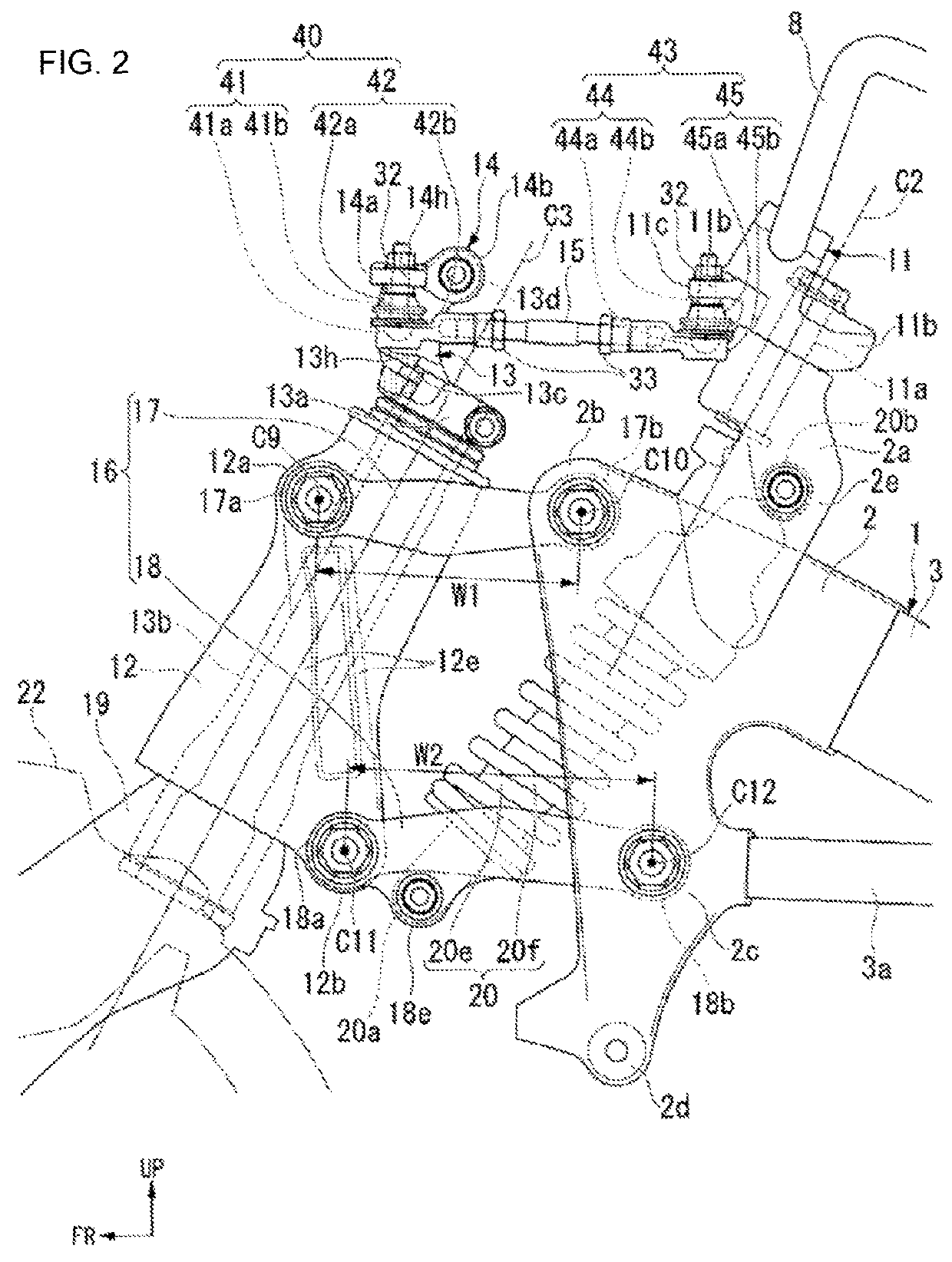
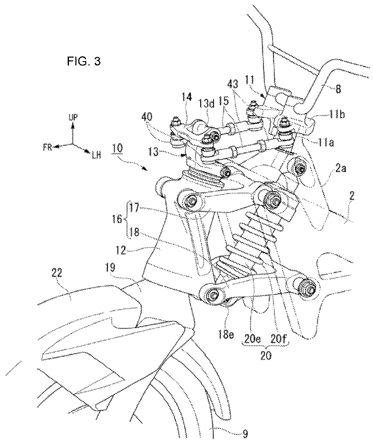
[0019]An embodiment of the present invention will hereinafter be described with reference to the drawings. Incidentally, directions such as a forward direction, a rearward direction, a left direction, a right direction, and the like in the following description are identical with directions in a vehicle to be described in the following unless otherwise specified. In addition, an arrow FR indicating the forward direction of the vehicle, an arrow LH indicating the left direction of the vehicle, an arrow UP indicating the upward direction of the vehicle, and a lateral center line CL of the vehicle are shown in appropriate positions in the drawings to be used in the following description.

[0020]FIG. 1 shows a front portion of a vehicle body of a motorcycle as an example of a saddle riding type vehicle. Referring to FIG. 1, a vehicle body frame 1 of the motorcycle has a front block 2 as a front end portion of the vehicle body frame 1 which front block 2 supports a front wheel suspension d...


PUM


Abstract

A front suspension structure includes a head pipe; an upper arm portion having a front end portion connected to the head pipe rockably about a first coupling axis and a rear end portion connected to a vehicle body frame rockably about a second coupling axis; and a lower arm portion disposed below the upper arm portion, and having a front end portion connected to the head pipe rockably about a third coupling axis and a rear end portion connected to the vehicle body frame rockably about a fourth coupling axis. The structure includes a cushion unit making a lower end portion perform a stroke as the lower arm portion rocks; the lower end portion supported in front of a middle point of a segment connecting the third coupling axis to the fourth coupling axis, and an upper end portion supported in a rear of the second coupling axis.

Description

FIELD OF THE INVENTION[0001]This application relates to a front suspension structure for a saddle riding type vehicle.BACKGROUND OF THE INVENTION[0002]One example of a conventional front suspension structure for a saddle riding type vehicle is disclosed in Japanese Patent Laid-Open No. Hei 4-169386 (“JP ‘386”). This structure supports a front fork and a vehicle body frame by front and rear end portions of an upper arm portion and a lower arm portion each extending longitudinally. As viewed from the side, a cushion unit is provided between the front and rear ends of the upper and lower arm portions.SUMMARY OF THE INVENTION[0003]One problem with the aforementioned structure of JP ‘386 is that when the cushion unit is disposed between the front and rear ends of the upper and lower arm portions as viewed from the side, distances between the front and rear ends of the upper and lower arm portions, that is, longitudinal lengths of the arm portions are increased, thus resulting in a large ...

Claims


Application Information

Patent Timeline
Patent Type & Authority Patents(United States)
IPC IPC(8): B62K25/24B62K21/00B62K25/12
CPCB62K21/00B62K25/24B62K25/12
Inventor KUWABARA, NAOKIISHIKAWA, JUNTODA, MUNEHIRO
Owner HONDA MOTOR CO LTD
Why Eureka
Try Eureka