Battery control circuit and battery device

a control circuit and battery technology, applied in the control arrangement of battery/fuel cell, electric devices, secondary cell servicing/maintenance, etc., can solve the problems of limited equalization only during the operation of the battery device, the deterioration of the battery is likely to progress in a high or low soc state, etc., to achieve the effect of suppressing the energy loss of the battery unit and simple process

Active Publication Date: 2016-06-07
HITACHI ASTEMO LTD
View PDF59 Cites 7 Cited by
  • Summary
  • Abstract
  • Description
  • Claims
  • Application Information

AI Technical Summary

Benefits of technology

[0011]According to the present invention, it is possible to realize a battery control circuit or a battery device control method capable of suppressing energy loss of a battery unit as much as possible with a simple process and a small number of commands.

Problems solved by technology

Moreover, when it is expected that the usable SOC changes over a wide range as in a PHEV or EV, deterioration of a battery is likely to progress in a high or low SOC state.
However, when a battery having a large capacity is required, in particular, there is a limit in the equalization only during the operation of a battery device depending on the degree of a voltage fluctuation.

Method used


Image

  • Battery control circuit and battery device
  • Battery control circuit and battery device
  • Battery control circuit and battery device

Examples


first embodiment

[0049]A first embodiment of the present invention will be described with reference to FIGS. 1 to 13.

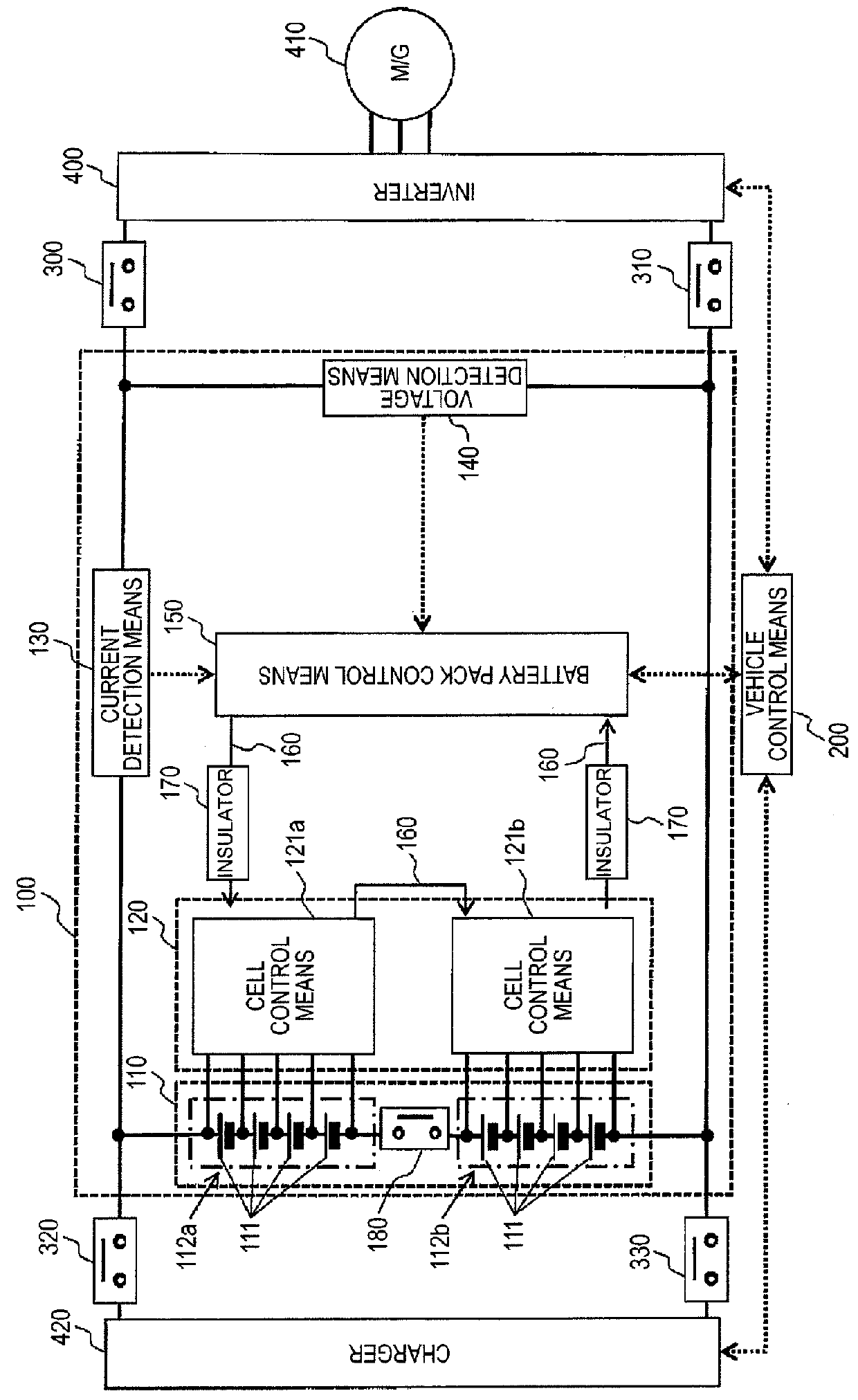
[0050]FIG. 1 illustrates a configuration example of a battery device of a plug-in hybrid vehicle according to the present embodiment.

[0051]First, a configuration of a battery device 100 will be described. The battery device 100 includes a battery pack 110 that includes a plurality of cells 111, cell management means 120 that monitors the state of the cell 111, current detection means 130 that detects a current flowing in the battery device 100, voltage detection means 140 that detects a total voltage of the battery pack 110, and battery pack control means 150 that controls the battery pack 110. The battery pack control means 150 receives a cell voltage and a temperature of the cell 111 transmitted from the cell management means 120, a current value flowing in the battery device 100 transmitted from the current detection means 130, and a total voltage value of the battery pack 110 tran...

second embodiment

[0134]The second embodiment of the present invention will be described with reference to FIGS. 17 and 18.

[0135]FIG. 17 illustrates a configuration example of a battery device 100 of a plug-in hybrid vehicle according to the present embodiment. In the present embodiment, two cells 111 are electrically connected in parallel to form a parallel cell 113, and eight parallel cells 113 are electrically connected in series to form a battery pack 110. Moreover, in the present embodiment, four parallel cells 113 are connected in series to form cell groups 112a and 112b.

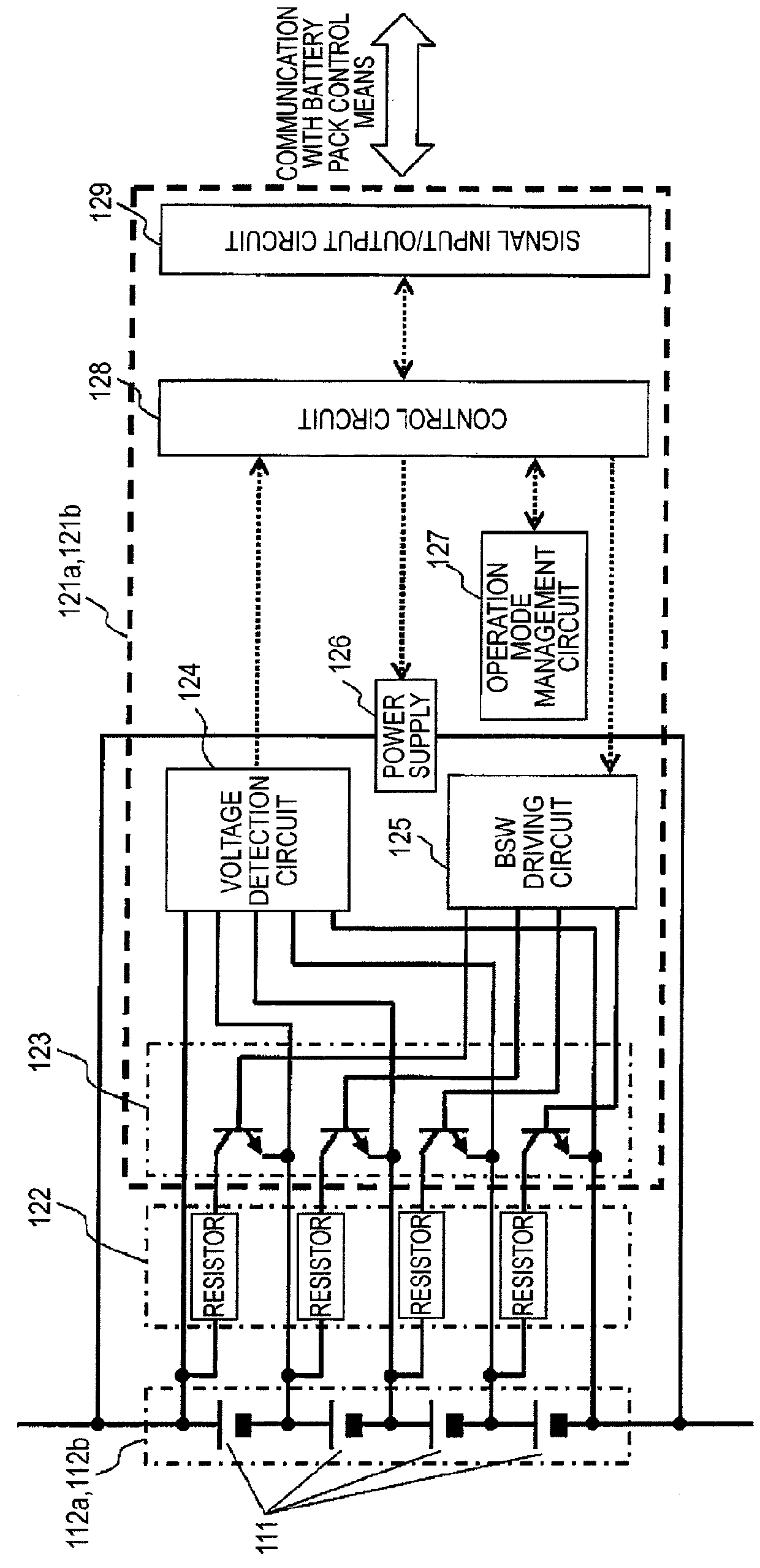
[0136]Cell control means 121a and 121b are allocated to the cell groups 112a and 112b that are grouped in this way. The cell control means 121a and 121b are connected in parallel to the cell groups 112a and 112b and monitor and control the state of the parallel cells 113 that constitute the cell groups 112a and 112b to which the cell control means 121a and 121b are allocated.

[0137]As described above, the present embodiment is ...

third embodiment

[0154]The third embodiment of the present invention will be described with reference to FIGS. 19 to 27. In the present embodiment, one cell control means 121 corresponds to one cell 111, and the state of one cell 111 is monitored by one cell control means 121. This is different from the first embodiment.

[0155]FIG. 19 illustrates a configuration example of a battery device 100 including a driving system of a plug-in hybrid vehicle according to the present embodiment. In the present embodiment, to simplify the description, similarly to the first embodiment, eight cells 111 form a battery pack 110.

[0156]Moreover, FIG. 20 illustrates a circuit configuration of the cell control means 121 according to the present embodiment. When one cell control means 121 is allocated to one cell, the voltages of cells 111 can be adjusted by only the discharge means 1 using the consumption current required for the operation of the cell control means 121. Thus, it is not necessary to use the discharge mea...


PUM

PropertyMeasurementUnit
output voltageaaaaaaaaaa
charge stateaaaaaaaaaa

Abstract

In a battery device including a battery pack in which a plurality of cells are connected in series, there are provided a battery control circuit or a battery device capable of eliminating a fluctuation in the voltage or charged state which can occur between the cells, or preventing the cells from being maintained in an over-charged state for a long period. A plurality of cell groups each including a plurality of cells are connected in series to form a battery pack. Cell controller is provided to the respective cell groups operate with electricity supplied from the cell groups allocated thereto so as to monitor and control the state of the cells of the cell group. Battery pack controller controls the cell controller based on information from the plurality of cell controller.

Description

TECHNICAL FIELD[0001]The present invention relates to a control circuit for a plurality of batteries that constitutes a battery unit and to a battery device.BACKGROUND ART[0002]In general, in a battery device that is mounted on an electric vehicle (EV), a plug-in hybrid vehicle (PHEV), and a hybrid vehicle (HEV), a plurality of batteries are connected in series to form a battery unit. Here, when individual differences between batteries such as a capacitance fluctuation or a self-discharge fluctuation between batteries occurs, a fluctuation in the charged state (State of Charge: SOC) of each battery included in the battery device may occur. When this fluctuation occurs, charge control is performed based on a battery having the highest SOC among the plurality of batteries, and discharge control is performed based on a battery having the lowest SOC. Thus, the energy that can be used by the battery unit decreases. Moreover, when it is expected that the usable SOC changes over a wide ran...

Claims


Application Information

Patent Timeline
Patent Type & Authority Patents(United States)
IPC IPC(8): H02J7/00H01M10/48H01M10/42B60L11/18H02J7/04B60L3/00H02J7/02
CPCH02J7/0021B60L11/1864B60L11/1866H01M10/4207H01M10/48H02J7/0016B60L2200/26H01M2010/4271H02J7/044Y02T10/7005Y02T10/7055Y02T10/7061B60L58/21B60L58/22Y02T10/70Y02E60/10H02J7/04H02J7/00716
Inventor NAKAO, RYOUHEIKAWAHARA, YOUHEIKUDOU, AKIHIKOEMORI, AKIHIKOSAKABE, KEI
Owner HITACHI ASTEMO LTD
Why Eureka
Try Eureka